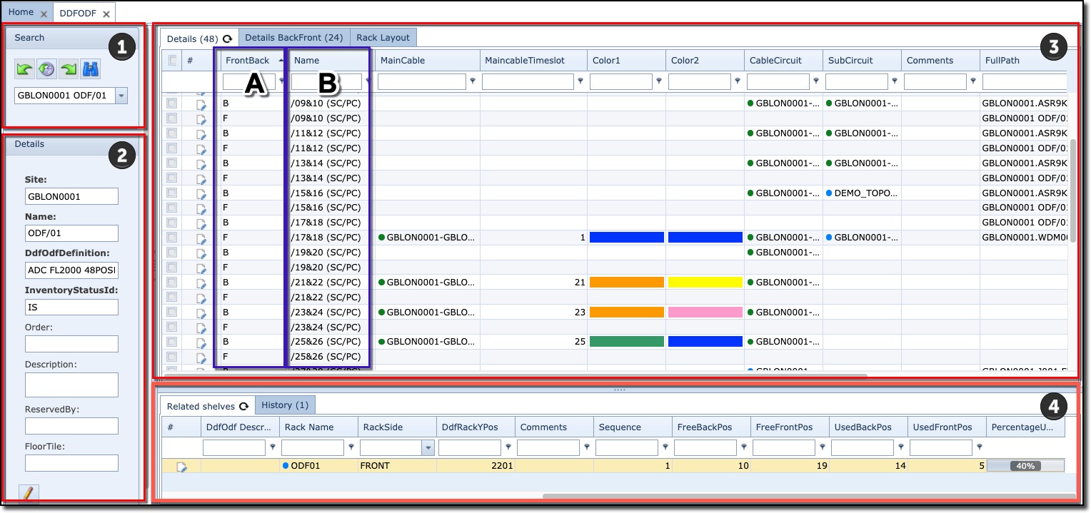
The DDF/ODF form is made up of 4 main areas of information.
1 |
Search field |
||
2 |
Details area (summary information) |
||
3 |
DDF/ODF/PP position details – with 2 or 3 tabs. |
||
▪ |
The Details tab page provides overall information about all patch positions in one grid/table. The Front and Back positions are separate rows as shown in the above screenshot in section labelled A The patch positions are labelled and shown in the above screenshot in section labelled B |
||
▪ |
The Details BackFront tab page provides information about all patch positions in one grid/table but each row contains information about the back and front positions. The left side of the table contains information about the BACK side, the right side of the FRONT side |
||
▪ |
A 3rd tab called Rack is displayed when DDF/ODF is contained in a rack or cabinet |
||
4 |
Related Shelves tabs |
Providing a list of other shelves of the same DDF/ODF/PP |
|
History tab |
List of historical actions related to this DDF/ODF/PP |
||
|
Each position of a PP/DDF/ODF has a back and a front side, see drawing below. Each front and back positions are listed as separate rows in the first tab page. Each front and back positions are listed on the same row in the second tab. |

More on the Details Tab:
TotalCbl1Length column - the calculated length is the total length of all the cbl1s used in the cable path plus the sum of all the slacks of the main cables.