Access Network Map
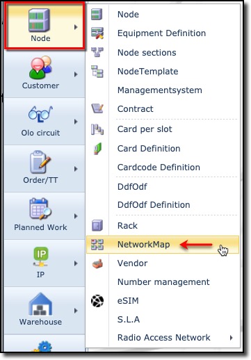
The Network Map functionality is accessed from the main menu bar, by selecting the Node object and then from the dropdown list provided, select the Network Map item.
Search for Network Maps
From the Search area in the Network Map form window
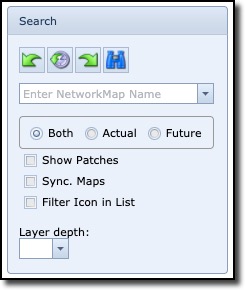
The search (pull-down) field is used to search for Network Maps matching the entered string in the field
or
when clicking the pull-down icon and using the name search field at the top of the column to filter your search
Both |
Show in map all objects with any status |
Actual |
Show in map all objects with non Planned status |
Future |
Show in map all objects with Planned status |
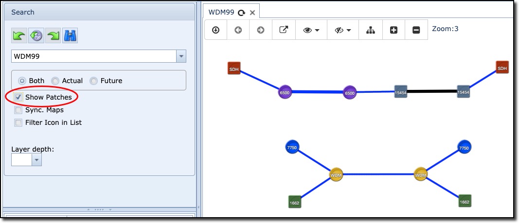
Show Patches |
Enabled: Show the intra-site connectivity on the Map at A and Z ends, between a set of equipment – how they are patched. Disabled: Show the connectivity on the map simply from the A to Z end – no intra-site patching lines shown |
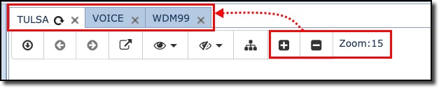
Sync. Maps |
Ensures that Zoom levels on all opened maps in Show Geo mode are normalised i.e., all zoom levels will be set to the same level chosen |
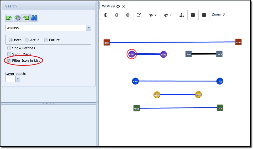
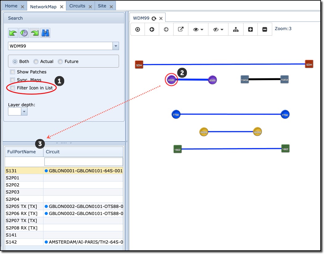
Filter Icon in List |
When enabled, it will hide port information from the display pane, when a node is selected (highlighted) on the map. |
Layer depth |
Determines the number of Sub circuit layers depth to show in the Sub circuit panel |
|
On opening an existing Network Map, it may not be in focus and therefore not visible. To remedy this, try clicking on the Show Geo option from the Map Display Options pull down list. |
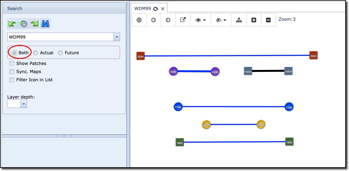
Both
This option will display all links no matter what status the underlying circuits are in. In this example nearly all links are in a Planned status, one link is black, showing that one of its underlying circuits could be In Service.
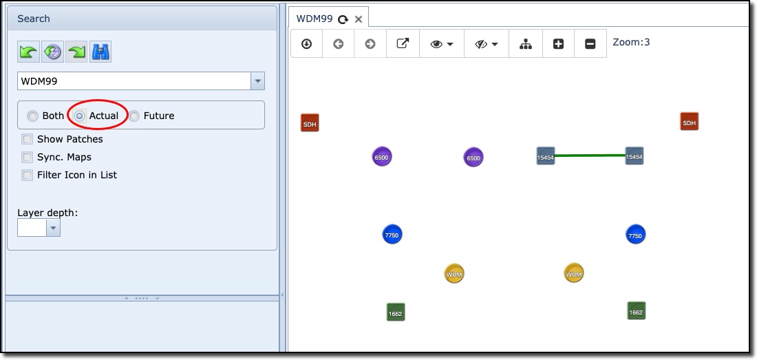
Actual
This option will display all links that are of status "In Service".
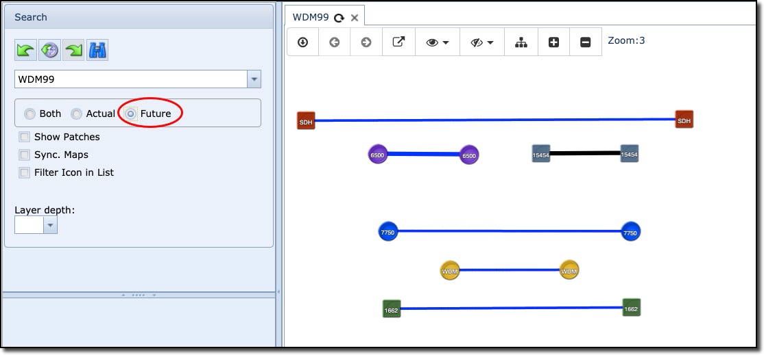
Future
This option will display all links that are of status "Planned". As you might notice, the link in black is showing that there is an underlying circuit in Planned status.
|
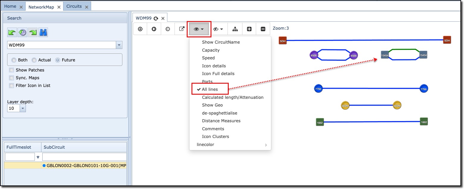
Be aware that a link shown in the map might contain Sub circuits, and these may have different status' themselves. If this is the case, then the link colour is shown as black. To verify this quickly, simply select All Lines from the Map Display Options feature. Here we see that one of the circuits in the ring is in status "In Service"
|
Show Patches
The Show Patches functionality displays how equipment is connected to each other. When not enabled, Show Patches displays how the devices are connected in an overall end to end manner.
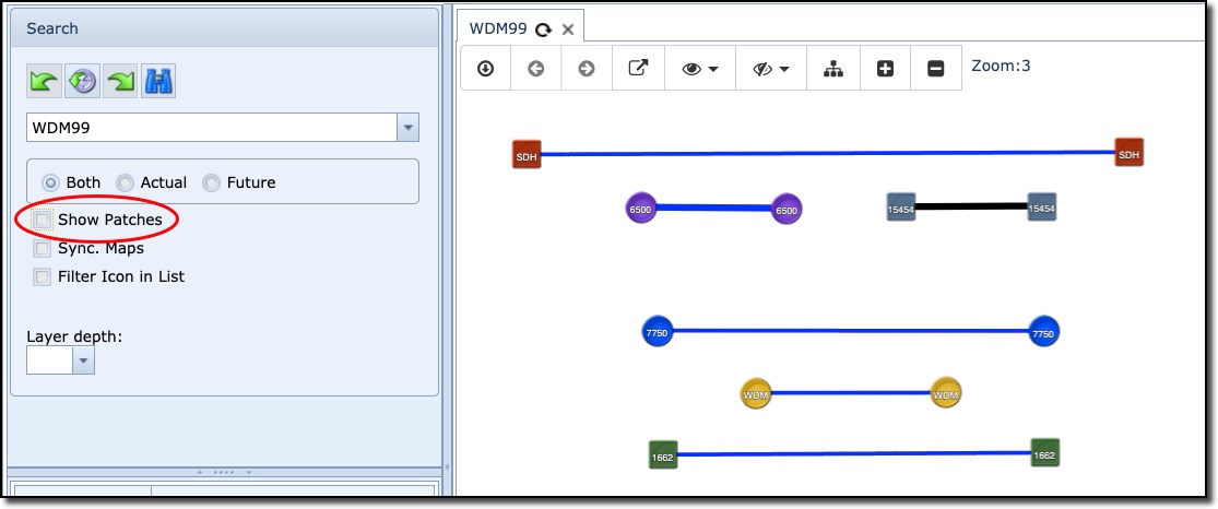
When enabled, Show Patches displays how the devices are connected on a link by link basis.
Sync. Maps
The Sync. Maps feature ensures that all opened maps are uniformly zoomed to the same level selected.
In this example, 3 maps are opened, the current actively displayed one (Tulsa) has been set to Zoom level 15, this means that VOICE and WDM99 maps will also be set to the same zoom level.
Filter Icon in List
The Filter Icon in List feature, when enabled, will hide a selected node's port details from being displayed in the Ports and Sub Circuits display area.
In the following example, the filter option is unselected (1), so when a node on the map is clicked (2), the result is to show all related ports (3) from that node.
In the next example the filter option is enabled and the result is, when the node on the map is clicked (highlighted), all related ports are hidden from display.