This next section will make use of all the knowledge you have gained in the previous chapters, by building several reports and relating them in such a way that a series of work order information can be produced in a single report.
This report will be visible and activated from the Order/TT object in IMS.

Figure 63 - Reporting Architecture
Three reports will be created of which one will be the master report calling on two sub-reports. The master report will be directly linked to the Orders/TT object form in IMS.
Two data sources will be relied upon; the Order Relate data source will provide the necessary data for the Circuit and Node based sub-reports. The Orders data source will provide data to the master report.
The creation of each report is repetitive and required tasks will flow as follows:
① |
Circuit Report |
Report Level Data Binding |
||
Report Design & Field Level Data Binding |
||||
② |
Node Report |
Report Level Data Binding |
||
Report Design & Field Level Data Binding |
||||
③ |
Order Report |
Report Level Data Binding |
Detail Margin Bar |
Pull in Circuit Report |
Pull in Node Report |
||||
Bottom Margin Bar |
||||
Report Design & Field Level Data Binding |
||||
Notice that in the last report, it calls the other two reports into the Detail Margin Bar.
① |
Create a Circuit Report |
This report will be called from the master WO-ORDERS report, and therefore is a subreport. It will not be associated directly to an IMS object, therefore no action is required for the tab called TabControlRelation.
The following screenshot gives an outline of the fields and toolbox elements used to control and contain the data for this report. We will be replicating this now.

Figure 64 - Circuit report
▪Create a new report, give it a name of WO-CIRCUITSX, and save it i.e., WO-CIRCUITS9
▪Navigate to and click on its Permissions tab, and locate your UserGroup name and enable your View, Update, and Delete options as in Figure 65
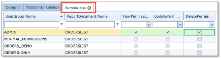
Figure 65 - Permissions Tab
▪Click on the Save Changes button in the lower right of the window
![]()
Figure - 66 Permissions Tab
The next set of steps will guide you through the data binding process. Firstly, we will set the report Level binding and then the Field Level binding.
Report Level Data Binding |
▪Click on the Designer tab
▪and then click on the Field List icon (cylinder)
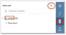
Figure 67 - Data Binding to orders
▪Click on the Add New Datasource icon – right of the ‘FIELD LIST’ label
▪From the dropdown list of data sources, select Orders
▪Highlight the ? Parameters line, Click on the Add Parameters icon - Figure 68

Figure 68 - Parameters
▪In the popup window, complete the following information:
oName: MainOrderId (link field in the data source)
oDescription: MainOrderId (any short description)
oType: select Number (32 bit integer) (matches the data source)
oVisible: enable
▪Click on the OK button in lower right corner

Figure 69 - Parameter Fields
▪Now save your overall progress so far by clicking the Save option from the Main Menu icon
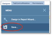
Figure 70 - Save
We will now have to provide some Properties information to complete the data binding and filtering to obtain the correct information when the report is finally run from the Orders object.
▪Click on the Properties icon to reveal the current Actions items
!! Ensure that you select your report name in the search field at the top (WO-CircuitsX), as we want to modify the properties at the report level
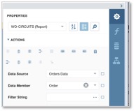
Figure 71 - Properties / Actions Items
We need to change the Data Member from Order to OrderRelate which creates an association between the required data sources
▪Click on the Data Members dropdown icon
▪Search for and select OrderRelate data source from the dropdown list
![]()
Figure 72 - Data Member - OrderRelate Source
▪Click on the Filter String item in the Actions grouping
▪Type in [RelatedCircuitId] > 0 And [Order.MainOrderId] = ?MainOrderId
oor you can click on the ellipsis icon (…) to open up the Filter Editor window, and build the filter as indicated in Figure 73
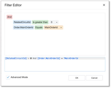
Figure 73 - Filter Editor
The result should look like this in the Properties section:
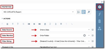
▪Go ahead and Save your progress so far.
Now that we have taken care of the data sources and binding aspects at report level, we can now proceed to add all the required control fields and toolbox elements to the Design Surface, and as stated earlier, data binding these at field level.
Report Design and Field Level Data Binding |
First we will create 3 Panels on the design surface; one in the Top Margin Bar and two in the Detail Bar. Panels are simple containers that we will use to group labels and their fields together.
The panel feature can be found in the side tool box bar as follows:
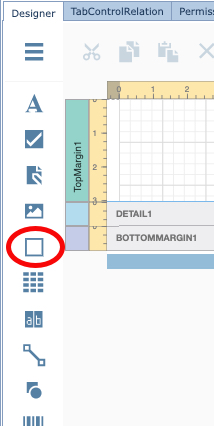
Drag and drop the three panels in a similar way as in the screenshot below - highlighted in blue

Below is a table containing the Field Names (where applicable), the field data source for binding purposes, and any toolbox element details necessary. Go ahead and place these on the design surface, and in their appropriate panels, and fill in the related properties.
|
Rather than dropping and dragging successive text fields from the Toolbox, try the Table |
Top Margin bar
Panel object: Panel1
Control Type / name (if applicable) |
Label / Circuit Report |
Detail bar
Panel object: Panel2
Control Type / name (if applicable) |
Expression/ Object Type |
Expression |
Other Detail |
Label/Circuit Name |
Text |
[RelatedCircuit.Name] |
|
EquipmentDrawing / |
Node |
[RelatedCircuit.NodeA.Id] |
Equipment Type: Node |
Line/ |
|
|
|
EquipmentDrawing/ |
Node |
[RelatedCircuit.NodeB.Id] |
Equipment Type: Node |
Label/ |
Text |
[RelatedCircuit.Speed.Name] |
|
Label/Site A |
Text |
[RelatedCircuit.SiteA.Name] |
|
Label/Node A |
Text |
[RelatedCircuit.NodeA.Name] |
|
Label/Shelf A |
Text |
[RelatedCircuit.PortA.Shelf.Name] |
|
Label/Port A |
Text |
[RelatedCircuit.PortA.Name] |
|
Label/ DDF/ODF A: |
Text |
[RelatedCircuit.PortA.OdfDdfDetail.CableDetails] |
|
Label/Site A |
Text |
[RelatedCircuit.SiteB.Name] |
|
Label/Node A |
Text |
[RelatedCircuit.NodeB.Name] |
|
Label/Shelf A |
Text |
[RelatedCircuit.PortB.Shelf.Name] |
|
Label/Port A |
Text |
[RelatedCircuit.PortB.Name] |
|
Label/ DDF/ODF A: |
Text |
[RelatedCircuit.PortB.OdfDdfDetail.CableDetails] |
|
Panel object: Panel3
Control Type / name (if applicable) |
Expression/Object Type |
Expression |
Other Detail |
Label/Circuit Name |
Text |
[RelatedCircuit.Name] |
|
Label/ Speed/Bandwidth |
Text |
[RelatedCircuit.Speed.Name] |
|
Label/Customer abbrev.: |
Text |
[RelatedCircuit.Customer.Name] |
|
Label/Customer full name: |
Text |
[RelatedCircuit.Customer.FullName] |
|
Label/Product Code |
Text |
[RelatedCircuit.Product.Name] |
|
Label/Order |
Text |
[RelatedCircuit.Order.Name] |
|
Label/GEO Location Site A |
Text |
|
|
GeoMapDrawing 1 |
Site |
[RelatedCircuit.SiteA.Id] |
Tile layer: OSM HiddenPolygonType: CANDIDATE |
GeoMapDrawing 2 |
Site |
[RelatedCircuit.SiteB.Id] |
Tile layer: OSM |
CircuitPathControl |
Circuit |
[RelatedCircuit.Id] |
Show Card: enable |
▪Go ahead and Save your progress so far.
This completes the creation of the Circuits (WO-CircuitsX) report and will now move onto creating the Nodes (WO-NodesX) report
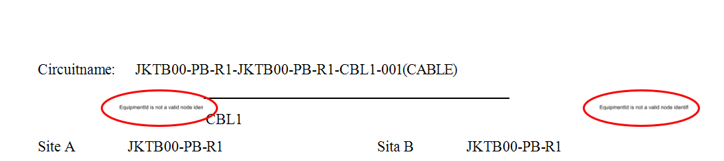
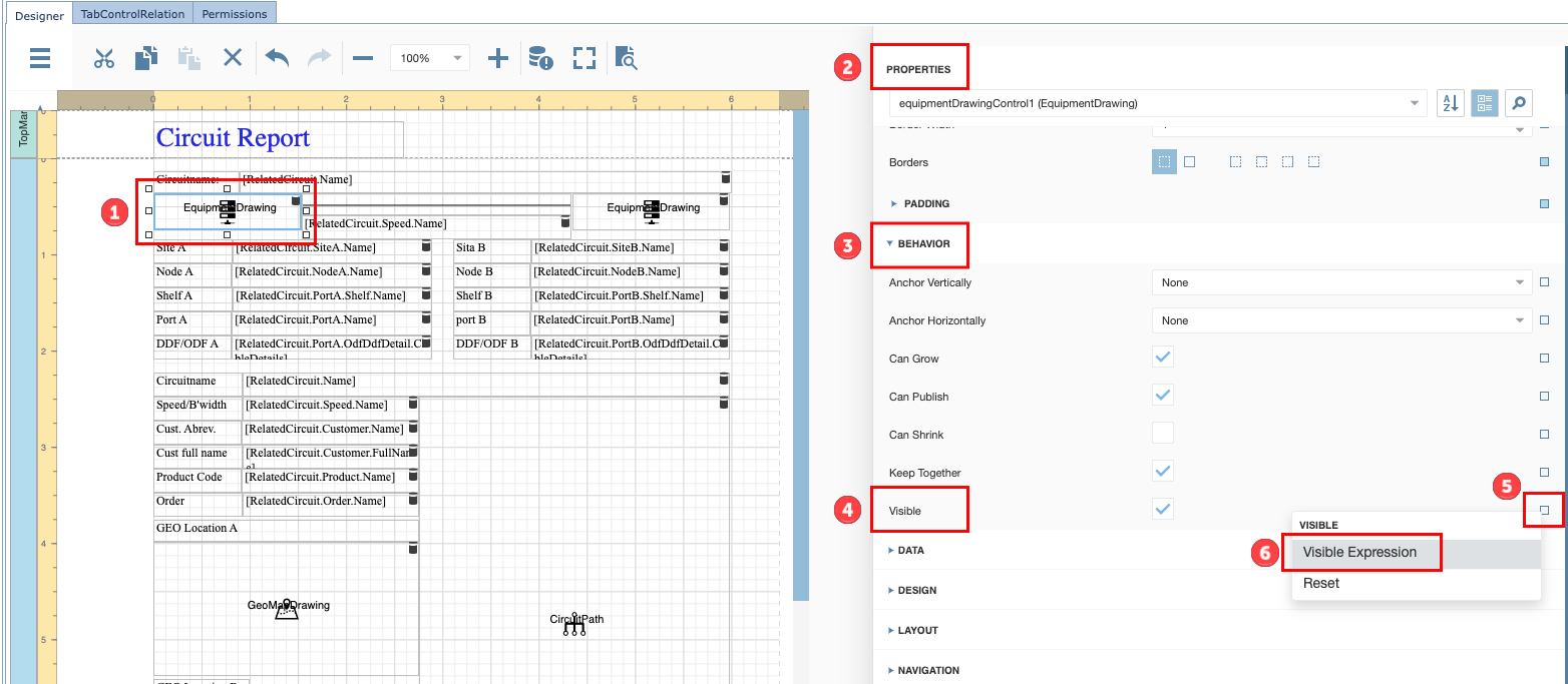
Tip:
|
This applies for any Graphical Image that may display a warning message due to missing data in the IMS object. Hiding warning or error display messages from the report due to missing graphics data i.e., Circuit that has no A or B side Node
|
▪ |
Follow the numbered steps as in this screenshot:
|
▪ |
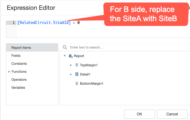
In the Expression Editor popup window type in the following and Save it:
|
② |
Create a Node Report |
This report will be called from the master WO-ORDERS report, and therefore is a sub-report. It will not be associated directly to an IMS object, therefore no action is required for the tab called TabControlRelation.
The following screenshot gives an outline of the fields and toolbox elements used to control and contain the data for this report. We will be replicating this now.

Figure 74 - Node Report
▪Create a new report, give it a name of WO-NODEX, and Save it.
▪Navigate to and click on its Permissions tab, and locate your UserGroup name and enable your View, Update, and Delete options as in Figure 75
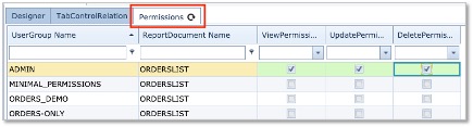
Figure 75 - Permissions Tab
▪Click on the Save Changes button in the lower right of the window
![]()
Figure 76 - Save Changes
The next set of steps will guide you through the data binding process. Firstly, we will set the report Level binding and then the Field Level binding.
Report Level Data Binding |
▪Click on the Designer tab and
▪and click on the Field List icon (cylinder)

Figure 77 - Data Binding to Order Data
▪Click on the Add New Datasource icon – right of the ‘FIELD LIST’ label
▪From the dropdown list of data sources, select Orders
▪Highlight the ? Parameters line, Click on the Add Parameters icon (+) Figure 78
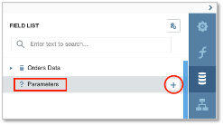
Figure 78 - Parameters
▪In the popup window, complete the following information:
oName: MainOrderId (link field in the data source)
oDescription: MainOrderId (any short description)
oType: select Number (32 bit integer)
oVisible: enable
▪Click on the OK button in lower right corner
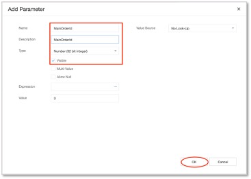
Figure 79 - Add Parameters
▪Now save your overall progress so far by clicking the Save option from the Main Menu icon
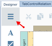
Figure 80 - Save your work
We will now have to provide some Properties information to complete the data binding and filtering to obtain the correct information when the report is finally run from the Orders/TT object.
▪Click on the Properties icon to reveal the current Actions items
Ensure that you select your report name in the search field at the top (WO-NODESX), as we want to modify the properties at the report level
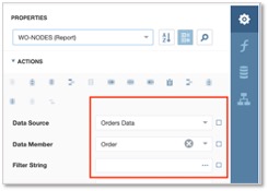
Figure 81 - Properties Actions Items
We need to change the Data Member from Order to OrderRelate which creates an association between the required data sources
▪Click on the Data Members dropdown icon
▪Search for and select OrderRelate data source from the dropdown list
![]()
Figure 82 - Data Member - OrderRelate source
▪Click on the Filter String item in the Actions grouping
▪Type in [RelatedNodeId] > 0 And [Order.MainOrderId] = ?MainOrderId
oor you can click on the ellipsis icon (…) to open up the Filter Editor window, and build the filter as indicated in Figure 83
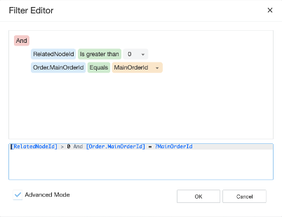
Figure 83 - Filter Editor
▪Go ahead and save your progress so far.
Now that we have taken care of the data sources and binding aspects at report level, we can now proceed to add all the required control fields and toolbox elements to the Design Surface, and as stated earlier, data binding these at field level.
Report Design and Field Level Data Binding |
Create only 1 Panel on the Detail Bar, for a reminder on how to do this, please refer to the previous section where
you added 3 panels to the previous report.
Below is a table containing the Field Names (where applicable), the field data source for binding purposes, and any toolbox element details necessary. Go ahead and place these of the design surface and fill in any related properties.
Detail bar
Panel object: Panel1
Control Type / name (if applicable) |
Expression/Object Type |
Expression |
Other Detail |
Label/Node |
Text |
[RelatedNode.Name] |
|
EquipmentDrawing/ |
RelatedNode |
[RelatedNode.Id] |
Equip.Expression: [Order.MainOrderId] HighlightedOrderId: [Order.MainOrderId]
|
Label/Node Name |
RelatedNode |
[RelatedNode.Name] |
|
Label/Equipment Definition |
RelatedNode |
[RelatedNode.EquipmentDefinition.Name] |
|
Label/Status |
RelatedNode |
[RelatedNode.InventoryStatusId |
|
Label/Site |
RelatedNode |
[RelatedNode.Site.Name] |
|
Label/Ring |
RelatedNode |
[RelatedNode.Ring.Name] |
|
Label/management System |
RelatedNode |
[RelatedNode.ManagementSystem.Name] |
|
Label/Domain |
RelatedNode |
[RelatedNode.Domain.Name] |
|
Label/Owner / Customer |
RelatedNode |
[RelatedNode.Customer.Name] |
|
▪Go ahead and Save your progress so far.
This completes the creation of the Nodes (WO-NodesX) report and will now move onto creating the Orders (WO-OrdersX) report
③ |
Create an Orders Report |
We now will create the final report which is the master report.
▪Create a new report, give it a name of WO-ORDERSX, and save it.
▪Navigate to and click on its TabControlRelation tab, and complete the details as in Figure 84
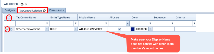
Figure 84 - Tab Control Relation
▪Click on the New icon as circled in red next to the TabControlRelation tab
Fill in the 5 columns of information as follows:
oTab Control name: OrderFormLowerTab
oEntityTypeName: Order
oDisplayName: i.e., WO-CircuitNodeRptX [displayed in the Object's GUI]
oAllUsers: <enable tick>
oColor: (colour of your choice)
▪Click on the green tick (circled in red) to save your tab work
Now we have to set the permissions for other users:
▪Navigate to and click on its Permissions tab, and locate your UserGroup name and enable your View, Update, and Delete options as in Figure 85
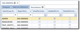
Figure 85 - Permissions Tab
▪Click on the Save Changes button in the lower right of the window
![]()
Figure 86 - Save Changes
The next set of steps will guide you through the data binding process. Firstly, we will set the Report Level Binding and then the Field Level Binding.
Report Level Data Binding |
▪Click on the Designer tab
▪and click on the Field List icon
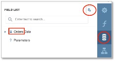
Figure 87 - Data Binding to Orders Data
▪Click on the Add New Datasource icon
▪From the dropdown list of data sources, select Orders
▪Click on the Add Parameters icon - Figure 88
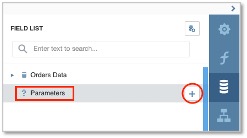
Figure 88 - Parameters
▪In the popup window, complete the following information:
oName: OrderId (link field in the data source)
oDescription: OrderId (any short description)
oType: select Number (32 bit integer)
oVisible: enable
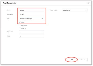
Figure 89 - Add Parameters
▪Click on the OK button in lower right corner
▪Now save your overall progress so far by clicking the Save option from the Main Menu icon
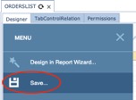
Figure 90 - Save your work
Now we switch to the Properties panel to set a filter to ensure the correct Order is retrieved.
▪In the Properties panel click on the Filter String item under the Actions group
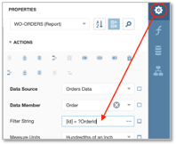
Figure 91 - Filter String
▪Type in [Id] = ?OrderId
oor you can click on the ellipsis icon (…) to open up the Filter Editor window, and build the filter as indicated in Figure 92.
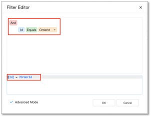
Figure 92 - Filter Editor
▪Go ahead and Save your progress so far.
Now that we have taken care of the data sources and binding aspects at report level, we can now proceed to the Details bar to complete the WO-ORDERS report.
Report Design and Field Level Data Binding |

First, let’s place the following elements in the Detail1 bar; the name of the Order, the WO-CIRCUITS (subreport1), and the WO-NODES (subreport2).
In the BottomMargin1 bar, we will again place a reference to the Order Name. In the TopMargin, you can place your company logo (real or imaginary)
(You should be familiar enough now to create a title for this report, in this example it is called Work Order, and given a modified text fonts, size, and colour)
Detail1 bar
▪Click on the Label icon in the Toolbox, and drag it onto the Details1 bar
▪Rename the Label to read Work Order
▪Click on the Label icon again in the Toolbox, and drag it onto the Details1 bar next to the Work Order Name field you just created
▪Click on this new label and navigate to the Properties panel
▪Modify its Text Expression field to contain: [Order.MainOrder.Name] as in Figure 93 ( and click the OK button
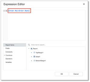
Figure 93 - Text Expression Field
Now we need to place two sub-report control fields in the Detail bar
▪Click on the Sub Report icon from the Toolbox, and drag it onto the Detail1 bar.
▪Repeat this again for the second sub-report and place it under the first sub-report
We now have to point these sub-report control fields to their respective reports created earlier.
▪Click on sub-report1 control field (Circuits), navigate to the Properties panel

Figure 94 - Report Source URL
▪In the Report Source Url item, search for and select your Circuits report created earlier – in this
example it is WO-CIRCUIT(X)
▪Click on the PARAMETER BINDINGS [+] item (under the DATA option) and fill in the following fields:
oParameter Name: MainOrderId
oBinding: Orders1 - Order.MainOrderId
The Binding field above can also be searched for from its dropdown list, but you will have to stretch the Properties panel wide (to the left) to see its contents properly, as per Figure 95
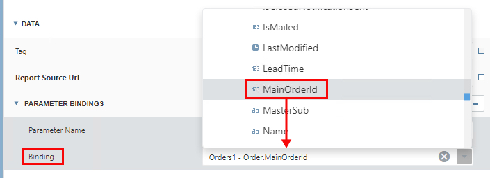
Figure 95 - Binding Details
▪Click on sub-report2 control field, navigate to the Properties panel
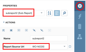
Figure 96 - Report Source URL
In the Report Source Url item, search for and select your Nodes report created earlier – in this example it is WO-NODE(X)
▪Click on the PARAMETER BINDINGS [+] item (under the DATA option) and fill in the following fields:
oParameter Name: MainOrderId
oBinding: Orders Data - Order.MainOrderId
The Binding field above can also be searched for from its dropdown list, but you will have to stretch the Properties panel wide (to the left) to see its contents properly, as per Figure 97.
Figure 97 - Binding Details
▪Locate the Page Break icon from the Toolbox, and drag it onto the Details1 bar, just above Subreport1 control field Figure 98. This will ensure that the two sub-reports that follow remain separated from the first page of information.
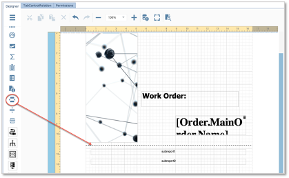
Figure 98 - Page Breakdown
▪Go ahead and Save your progress so far.
Now we will move onto designing the BottomMargin bar
BottomMargin bar
▪Click on the Label icon in the Toolbox, and drag it onto the BottomMargin1 bar
▪Click on this new control field and navigate to the Properties panel.
▪Click on the Text item’s option icon and add [Order.MainOrder.Name] in the Expression Editor popoup window
▪Go ahead and Save your progress so far.
The Final Step
The final step is to complete the Binding Expression field found in the TabControlRelation tab

Figure 99 - Parameter and Binding Details
▪Click on the editing icon (circled red in Figure 99.
▪In the BindingExpression field type in Id – linking the data source to the field
This should now look as follows
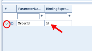
Figure 100 - Binding Expression
▪Click on the green tick to save your tab work
This completes the WO-ORDER report and all the required exercises to run this report.
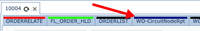
All that is left to do now is to test the report by running it from the Orders object in IMS and with an Order/TT instance opened in the GUI, scroll to the rightmost edge of the Order/TT’s tab bar and locate the Tab with the name of the report just created.
Click on it to reveal the report. In some cases, there is a slight delay whilst the report is being generated.
Any faults can now be addressed and rectified, and text formatting and resizing activities can be carried out to tailor it to your specifications.