This chapter describes several way in which to create Circuits in IMS and are explained in detail below.
The following sections can be found in this chapter:
➢Method 1 - CircuitForm Actions Button Bar
➢Method 2 - Network Map - Selecting Nodes
➢Method 3 - Right Mouse Click on Circuit Name
➢Method 4 - Network Map - Circuit Drawer
➢Method 5 - Duplicate a Circuit
➢Add a circuit to carrier connection / add sub-connection
➢New Connection Popup Window
Method 1 – CircuitForm Actions Button Bar
Selecting the New button from the button bar; either from unopened or opened circuit form
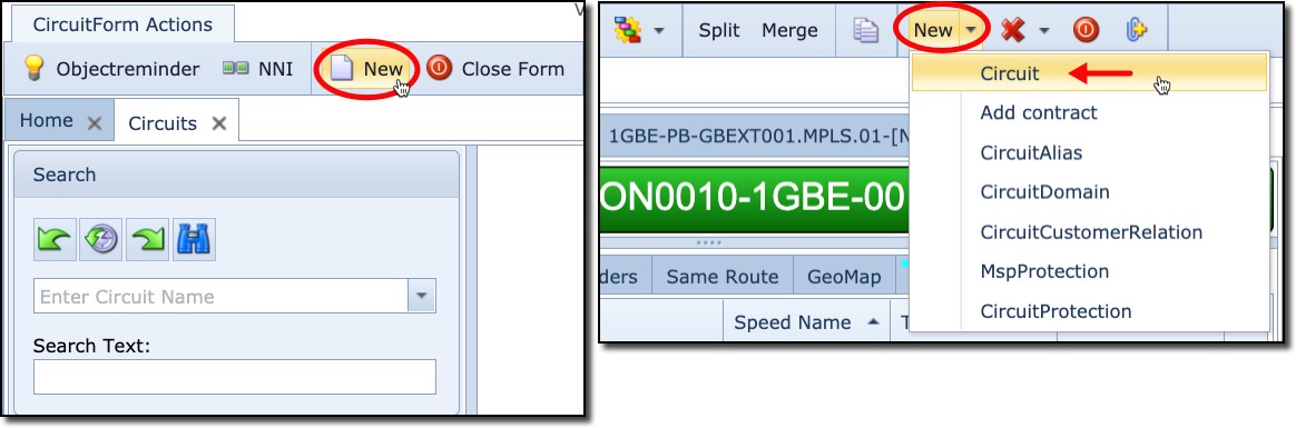
This opens up the create Circuit popup window to be filled in accordingly. Refer to the last section in this chapter called New Connection Popup Window.
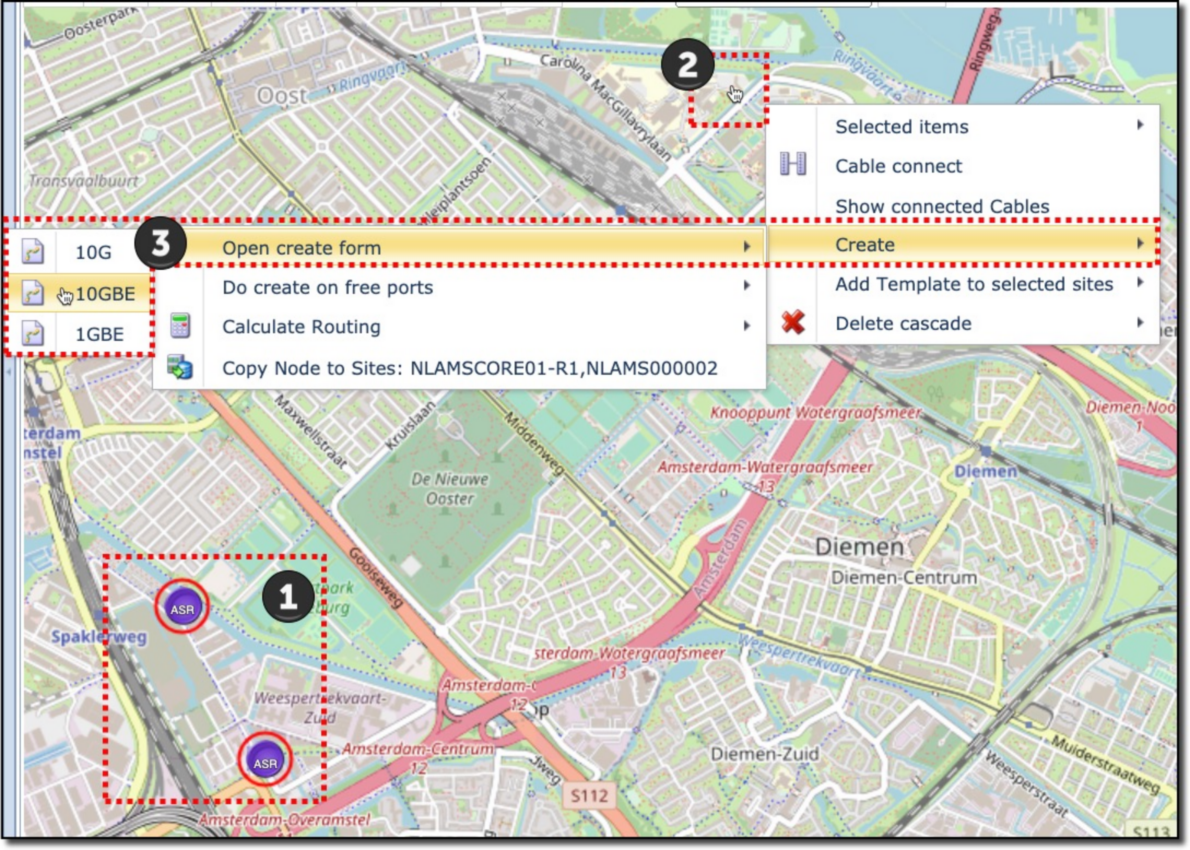
Method 2 – Network Map - Selecting Nodes
Select the appropriate Network Map:
1 |
Shift+Left Mouse Click on two relevant locations on the map – both locations will show a red circle around them when selected |
2 |
Right Click on the map background – this reveals a popup list window |
3 |
Select the following options: •Create, then •Open Create form – this opens up any technology appropriate circuit speeds on a case by case basis •Choose and select the required Speed option |
This opens up the create circuit popup window to be filled in accordingly. Refer to the last section in this chapter called New Connection Popup Window.
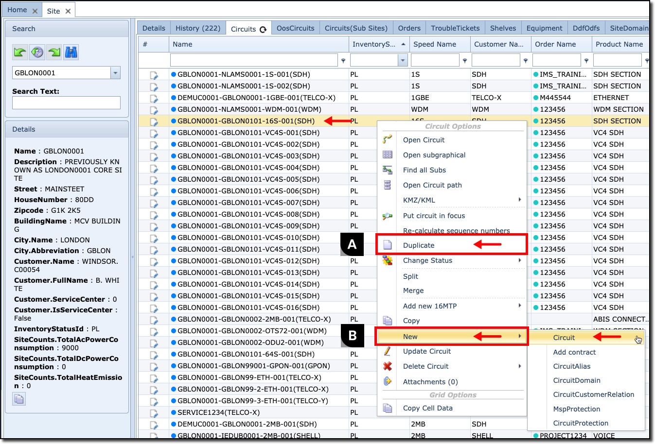
Method 3 – Right Mouse Click on Circuit Name
Duplicate or New
On a list of Circuits, say, from a Node or Site object:
▪ |
Right Mouse Click on the required Circuit name – a dropdown list appears |
▪ |
Choose (A) Duplicate to create a new Circuit with a pre-filled creation form with the same parameters as the Circuit that was clicked - See below for a more detailed instruction under section Method 5 – Duplicate a Circuit |
▪ |
Choose (B) New for a blank Circuit creation form |
Fill in the required information in the Circuit popup window. Refer to the last section in this chapter called New Connection Popup Window.
Method 4 – Network Map - Circuit Drawer
Locate the required Network Map and from its button bar:

▪ |
Select the Create New icon |
▪ |
Locate the first node on the map and left click it to reveal a drop down list of ports - you may need to scroll down - and select the required port |
▪ |
Locate the second node on the map and left click it to reveal a drop down list of ports - you may need to scroll down - and select a free port of the same/similar port speed |
This will produce a Create Circuit popup window that is pre-filled with data from the selected ports.
▪ |
In the popup window select the required order name from the Order field drop down list |
▪ |
Review the rest of the popup details and click the Save icon when finished |
If the line representing the connection between the two nodes is not visible, then the node's Map Settings need to be adjusted. One or both of the node's Map Setting will need to be adjusted.

▪ |
Select the group of nodes and right click on them |
▪ |
Select the required node name - confirmed in the grey information box |
▪ |
Select Map Settings at the foot of the drop down list - which produces a popup window - click on the edit icon (pencil) |
▪ |
In the PhysicsSpeeds field type in the name of the speed i.e., 1GBE. If more speeds need to be shown in future then add more speeds with the 'pipe' separator between them i.e., 1GBE|10GBE |
▪ |
Click on the Save icon to finish and close the popup window and refresh the Network Map to reveal the connectivity (binocular icon) |
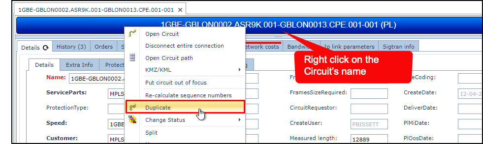
Method 5 – Duplicate a Circuit
Another way to easily create a new connection is to duplicate an existing circuit. This is typically performed when most of the existing Circuit parameters will be used in the new Circuit.
▪ |
Locate and right click on the object reminder or any other grid or table where the circuit name is visible |
▪ |
From the drop down list choose Duplicate |
This reveals a Duplicate Circuit popup window. Modify any field details as required |
|
▪ |
Make sure the node or shelf details are filled in correctly |
▪ |
Update or fill in the port details if this is a physical connection. |
▪ |
For logical connections, fill in the node or shelf end point details but not the ports |
▪ |
Click on the Save icon when finished |
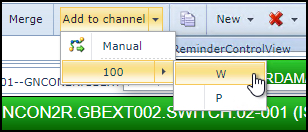
Add a circuit to carrier connection / add sub-connection
Circuits can be added to Carrier Circuits i.e., V-LAN into a 1GBE connection, or 2MB into a VC4 connection.
▪ |
Locate the Circuit to be added to a Carrier circuit, and put it In Focus. |
▪ |
Locate the Carrier Circuit and from the Circuit Form Actions button bar select the Add to channel option - alternatively right click on the Carrier name bar and select the same option. |
▪ |
Depending on the Carrier's channelisation - select the available channel |
New Connection Popup Window
The next screenshot shows an example and field description of a New Connection popup window.
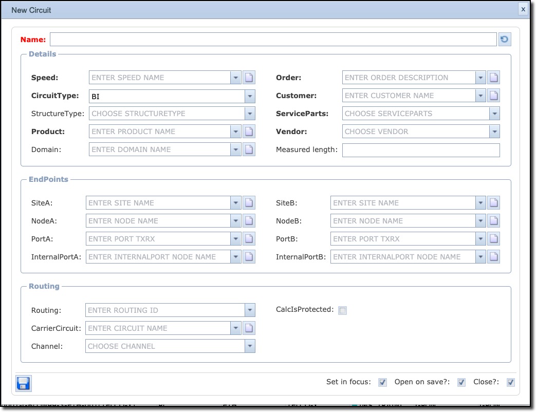
The following is a list of fields and brief description of the Circuit form:
Name |
Circuit name – prefilled using other fields below |
Direction |
|
Details section |
|
Speed |
Speed/Bandwidth of circuit (Circuit type) |
CircuitType |
BI (bi-directional) or UNI (uni-directional) -
|
StructureType |
Circuit Structure Type in case a connection has a fixed structure that must be registered. |
Product |
Product Code/Service name related to the circuit |
Domain |
IP domain (if applicable) |
Order |
Work Order number |
Customer |
Customer or platform name (Circuit Owner) |
ServiceParts |
Service Parts/Platform name |
Vendor |
Network Vendor |
Measured length |
Length of connection, measured. |
EndPoints section
|
|
SiteA |
Site name of A end of circuit |
NodeA |
Node name of A end of circuit |
PortA |
Port name of A end of circuit |
InternalPortA |
Internal port name of A-end of circuit |
SiteB |
Site name of B end of circuit |
NodeB |
Node name of B end of circuit |
PortB |
Port name of B end of circuit |
InternalPortB |
Internal port name of B-end of circuit |
Routing section
|
|
Routing |
An ID field used in case a calculated routing is available using auto routing functionality |
CarrierCircuit |
Name of the carrier circuit (if applicable) |
Channel |
Number of the channel on the carrier circuit (if applicable) |
CalcIsProtected |
Tick box indicating this connection is protected, so that auto routing considers this as a protected route. |