Open DdfOdf Definition form.
To open the DDF/ODF definition form, use the menu on the left, “Node” option DdfOdfDefinition.

Find DdfOdf Definition information
To find existing DDF/ODF definition, use the search field in section1 (screenshot).

The following details are shown on the left (section 2 in screenshot):
Name |
Name of DDF/ODF definition |
DDFKind |
Kind of DDF/ODF, DDF (digital/copper) or ODF (optical) |
Type |
BI or UNI (directional) |
NumberOfX |
<currently not used yet> |
NumberOfY |
<currently not used yet> |
Height |
Height of DDF/ODF (shelf) |
Width |
Width of DDF/ODF (shelf) |
Depth |
Depth of DDF/ODF (shelf) |
DefPhysSpeeds |
Connection Speed/type setting for showing connecting connections/cables in the Network Map. |
Shape |
Shape icon type for showing the DDF/ODF in the Network Map. |
ShapeColor |
Shape icon color for showing the DDF/ODF in the Network Map. |
ShapeText |
Shape icon text for showing the DDF/ODF in the Network Map. |
NameTemplate |
Naming convention rule for (creating) new DDF/ODF’s Examples: [DDFODFDEFINITION.DDFKIND].[NUM:4] (this takes the field Ddfkind, then a dot and then a 4 digit sequence number)
ODF[NUM:3] (this takes fixed “ODF”, then a 3 digit sequence number)
|
In section 3 (screenshot) the following fields are visible in a grid/table.
Patchpoint name |
Name of the patchpositions(s) |
DdfOdfDefinition |
Name of DDF/ODF definition |
InterfaceDefinition |
Interface type (e.g. SC/PC, BNC, RJ45, etc) |
X |
<currently not used yet> |
Y |
<currently not used yet> |
Sequence number |
Sequence number to order the patch positions in correct order on the screen. |
Button bar in the DdfOdfDefinition form
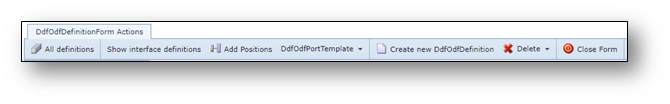
All definitions |
Lists all DdfOdfDefinitions on the screen |
Show interface definitions |
Lists all Interface Definitions on the screen |
Add positions |
To add new patch positions |
DdfOdfPortTemplate |
|
Create new DdfOdfDefinition |
To create a new DDF ODF definition |
Delete |
Delete the DdfOdfDefinition opened on the screen |
Close form |
Closes the form |
Create new DDF/ODF Definition
To create new DDF/ODF Definition, press “Create new DdfOdfDefinition” button.
A popup menu appears.
Fill in the following information
The following details are shown on the left (section 2 in screenshot):
Name |
Name of DDF/ODF definition |
DDFKind |
Kind of DDF/ODF, DDF (digital/copper) or ODF (optical) |
Type |
BI or UNI (directional) |
NumberOfX |
<currently not used yet> |
NumberOfY |
<currently not used yet> |
Height |
Height of DDF/ODF (shelf) |
Width |
Width of DDF/ODF (shelf) |
Depth |
Depth of DDF/ODF (shelf) |
DefPhysSpeeds |
Connection Speed/type setting for showing connecting connections/cables in the Network Map. |
Shape |
Shape icon type for showing the DDF/ODF in the Network Map. |
ShapeColor |
Shape icon color for showing the DDF/ODF in the Network Map. |
ShapeText |
Shape icon text for showing the DDF/ODF in the Network Map. |
NameTemplate |
Naming convention rule for (creating) new DDF/ODF’s Examples: [DDFODFDEFINITION.DDFKIND].[NUM:4] (this takes the field Ddfkind, then a dot and then a 4 digit sequence number)
ODF[NUM:3] (this takes fixed “ODF”, then a 3 digit sequence number)
|
Press save.
Create new patch positions
To create new/additional patch positions, press button “Add positions”:
Fill in the following information:
First Patchpoint name |
Name of the first patch positions |
DdfOdfDefinition |
Name of DDF/ODF definition |
InterfaceDefinition |
Interface type (e.g. SC/PC, BNC, RJ45, etc) |
Sequence number |
Sequence number to order the patch positions in correct order on the screen. |
X |
<currently not used yet> |
Y |
<currently not used yet> |
Number of patchpoints |
Number of patch points that need to be created. |