Open DDF/ODF Definition
The DDF/ODF form can be opened from the IMS Main Menu:
▪From the Node option, click on the DdfOdf Definition option from the list provided

Search for a DDF/ODF Definition
Existing DDF/ODF Definitions can be found using the search field on the left of the screen.
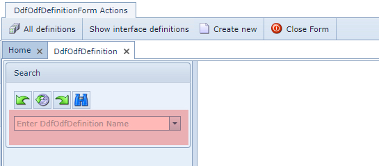
DDF/ODF Definition form

The DDF/ODF Form is made up of 3 sections and are described as follows:
|
The first section is the Search area and is described in the previous section of this page. |
|
The second section contains the Details of the definition and the fields of information are described as follows: |
Name |
Name of the DDF/ODF definition |
DDFKind |
The kind of DDF/ODF: DDF (digital/copper) or ODF (optical), NoSplice, etc. |
Type |
Direction indicator: BIdirectional or UNIdirectional |
NumberOfX |
<currently not used yet> |
NumberOfY |
<currently not used yet> |
Height |
Height of DDF/ODF (shelf) |
Width |
Width of DDF/ODF (shelf) |
Depth |
Depth of DDF/ODF (shelf) |
DefPhysSpeeds |
Connection Speed type setting for showing connections/cables in the Network Map |
Shape |
Shape icon type for showing the DDF/ODF in the Network Map i.e. circle |
ShapeColor |
Shape icon color for showing the DDF/ODF in the Network Map i.e. steel |
ShapeText |
Shape icon text for showing the DDF/ODF in the Network Map i.e. DDF |
ShapePicture |
Shape icon used for the Cable Route / Circuit Path information |
NameTemplate |
Naming convention rule for new DDF/ODFs Examples: [DDFODFDEFINITION.DDFKIND].[NUM:4] (this takes the field Ddfkind, then a dot separator and then a 4 digit sequence number) ODF[NUM:3] (this takes fixed “ODF”, then a 3 digit sequence number)
|
DdfOdfDefinitionImage |
Image that represents this definition when viewed from Node feature |
|
The third section contains the following grid fields of information: |
Patchpoint name |
Name of the patch positions in the frame |
DdfOdfDefinition |
Name of this DDF/ODF definition |
InterfaceDefinition |
Interface type i.e., SC/PC, BNC, RJ45, etc. |
X |
<currently not used> |
Y |
<currently not used> |
Sequence number |
Sequence number of the patch positions in their correct order |
DDF/ODF Definition Button Bar
![]()
All definitions |
Lists all DdfOdfDefinitions on the screen |
Show interface definitions |
Lists all Interface Definitions on the screen |
Generate bulkloader template |
Produces a formatted spreadsheet ready for users to populate which can then be loaded into the IMS database |
Add positions |
Produces a popup window to be filled in for adding new patch points to this DDF/ODF Definition |
DdfOdfPortTemplate |
Produces a popup window to be filled in for creating a new port template for any DDF/ODF Definition |
Create new DdfOdfDefinition |
To create a new DDF/ODF Definition instance - see the next section for details |
Delete |
Delete the opened DDF/ODF Definition form |
Close form |
Closes the opened DDF/ODF Definition form |
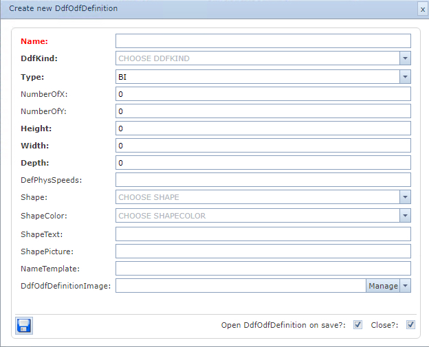
Create a new DDF/ODF Definition
From the DdfOdfDefinitionForm Actions button bar:
▪Click on the Create new option
This opens up the Create new DdfOdfDefinition popup window.
▪Fill in the required fields of information, in particular the mandatory ones.
The detailed field information is available above under the section called DDF/ODF Definition Form
▪Click on the Save icon in the lower left corner of the popup window when finished.
Create new Patch Positions
From the DdfOdfDefinitionForm Actions button bar:
▪Select the Add Positions option
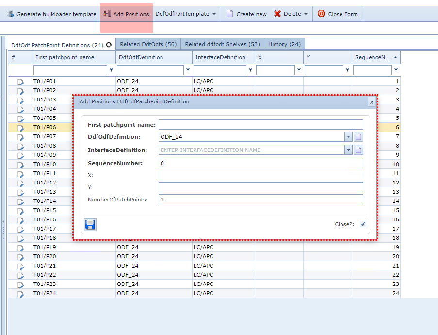
This opens up the Add Positions DdfOdfPatchPointDefinition popup window
▪Fill in the required information, in particular the mandatory fields
▪Click on the Save icon in the lower left corner of the popup window when finished
The following describes the fields of information available in the popup window:
First patchpoint name |
Name of the patch positions in the frame |
DdfOdfDefinition |
Name of this DDF/ODF definition |
InterfaceDefinition |
Interface type i.e., SC/PC, BNC, RJ45, etc. |
X |
<currently not used> |
Y |
<currently not used> |
NumberOfPatchPoints |
Set the number of new patch positions to add |