Introduction
Although the aim of this document is to describe the Sub Node feature, it is not intended to give
an in-depth explanation into a specific solution or use case. Having said that, and in
order to more fully explain how it could be used, we complete the Sub Node feature by
showing how it can be associated with other IMS objects, like Circuit paths.
The Sub Node feature in IMS is a flexible inventory component that allows for the modeling
of technologies such as multi-protocol label switching (MPLS) where a router not only performs
switching but also routing and bridging activities.
While some routers may perform these functions within its own platform, others may connect to
and use different devices. Whichever way, the Sub Node feature allows for the creation and
association between physical nodes as well as virtual objects.
The following example shows how the Sub Node feature is used to model an MPLS VLAN Aggregation
network, in essence a physical and logical node relationship.
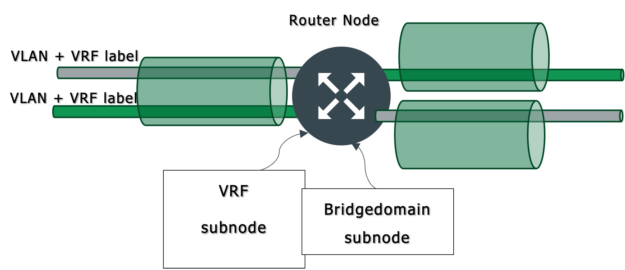
Sub Node … as a Bridge Domain
Although this is a node element in IMS, form a logical perspective, a Bridge Domain object
represents the linking and filtering aspect of packet switching in a VLAN technology environment.
VLANS are a Layer 2 protocol.
In this example a bridgedomain node will contain a reference back to its parent node. It will
also contain related VLAN circuit information.
Such information can be any related physical port names, virtual ports the circuit uses on that
physical port, and the Ethernet Service, which in this case is carrying IP traffic over a layer 2
network.
Sub Node … as a VRF
Devices that handle Virtual Routing and Forwarding (VRF) technology are ones that allow for
multiple instances of a routing table to co-exist within the same router at the same time.
The VRF resolves the potential overlapping IP address issue by using VRF header labels that
ensure that routing table entries remain unique. VRF handles the Layer 3 protocol – MPLS is a
layer 3 protocol.
A VRF node will contain a reference back to its parent node. It will also contain related MPLS
level circuit and port information as circuits are associated to it.
In the following sections we will explain:
•A reminder to create appropriate equipment definitions (section 1)
•How to then associate these equipment definitions in a hierarchy (section 2)
•How to associate Sub Node instances in a hierarchy (section 3)
•Show circuits mapped to these different node objects (section 4)