Equipment that appears on the Network Map can be selected to reveal detailed information without having to leave the map.
Node Popup
On an open Network Map:
▪Left click on a node icon - this will become circled in red
▪The node's popup appears with the following tabs of information:
oPorts - shows Port Name and Circuit columns
oDrawing - shows the equipment, including manhole butterfly view, in graphical form

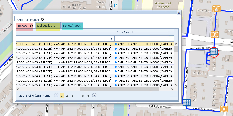
DDF/ODF Popup
On an opened Network Map:
▪Left click on a DDF/ODF icon - this will become circled in red
▪The DDF/ODF's popup appears with the following tabs of information:
oPatch Panel - shows Front Back, Full Name, Full Path, and Cable Circuit columns
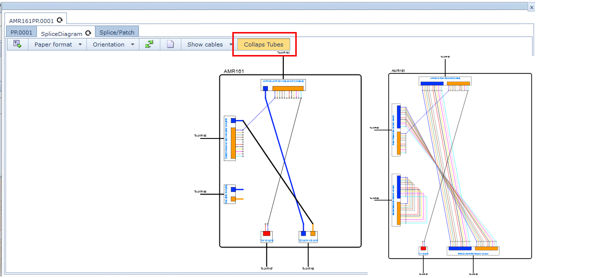
oSplice Diagram - shows intra device connectivity details in a graphical form with export to a PDF file
capabilities - see the section bellow called Splice Diagram for more information
oSplice/Patch - shows intra device connectivity details in text format - front and back patching
Splice Diagram
Various sections of information are available from the Splice Diagram tab.
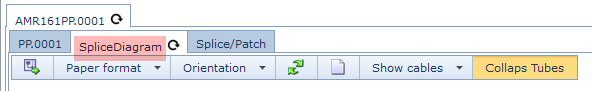
From left to right:
Export Splice Diagram:
Selecting this option will open up another tab in the current browser of a PDF document of the Splice Diagram in the current collapsed or expanded state - see section bellow called Collapse Tubes
Paper Format:
Sets the output size format for the exported Splice Diagram - Options are A4, A3, A2
Orientation:
Sets the output orientation for the exported Splice Diagram - Options are Portrait, Landscape
Refresh:
Updates all the equipment details relevant to this device and feature. Changes may have occurred to this device since the popup was opened and this ensure that the most current view is displayed i.e., cables and intra node fibre connectivity.
Create New DDF/ODF:
Opens up a popup window to create a new DDF/ODF at the current site.
Show Cables:
Selecting this tab produces a drop down list of all Cables that connect this device to others.
Clicking on this tab collapses and expands the view of fiber connectivity between patch points/ports within the frame or panel. The collapsed view is a single line connection, whilst the expanded view shows each individual strand in the connectivity.
Splice Patch
A more detailed view on how fibres are connected and patched between devices.
As explained in the above two sections, when a piece of equipment on the network map is clicked, it produces a popup window with detailed information.
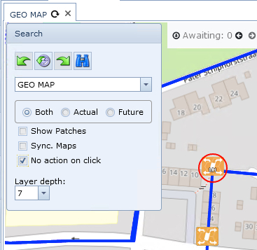
Depending on the work being carried out using IMS, it may not be desired to have the popup information always displayed, so it is possible to disable this feature as follows -
On an opened network map and in the Search area:
▪Click on (enable) the No action on click option