The Circuit Form allows the management of all types of network connections like physical connections,
logical circuits and services. By creating relations between circuits, it also allows the full mapping of all the
network layers from the cables to the physical network layers, to the logical network layers up to the network
and customer services.
In general, based upon the relations between circuits and/or node ports the circuit can be one of the following:
1.Physical connection if it has physical ports.
2.Logical connection if it has 1 or more carrier physical or logical connections.
3.Customer Service if it is a service (connection) for a customer.
Please note that a physical connection for a network like MPLS or SDH can be carried via a logical connection
in a network like WDM.
Open Circuit Form
To open the Circuit Form, select option “Circuit” from the Circuit menu on the left.
Find Circuit
To find an existing circuit/connection, use the search field. 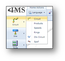
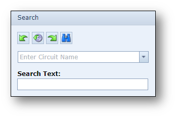
The search (pull-down) field is used to search for circuits matching the entered string in the field or when pressing
the pull-down button is used to look for circuits based on filters.
The Search Text field is used to search for circuits that contain part of the entered string in their circuit name.
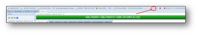
Information in the Circuit Form
The screenshot below gives an overview of the Circuit Form divided into multiple sections which have been
highlighted, numbered and briefly explained below.
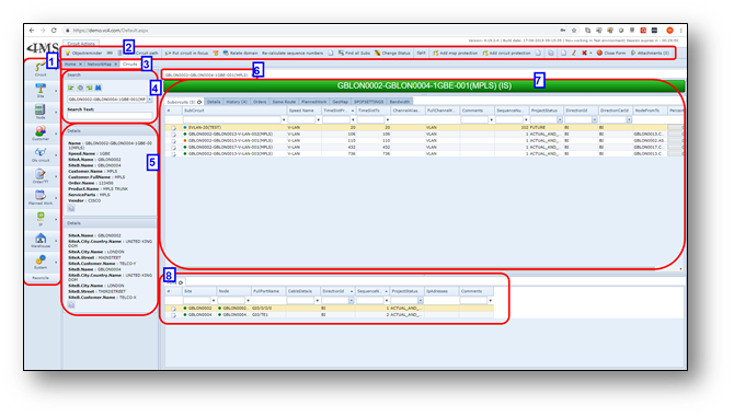
1 |
The main IMS button bar |
2 |
The buttons related to the opened form giving the user access to the form related functions. |
3 |
The currently opened forms |
4 |
The search area located on all the different forms in IMS |
5 |
The details of the active (opened) circuit within the form |
6 |
The opened circuits which have been kept for easy access |
7 |
The opened circuit in this form, listing the connection details and carrier and sub traffic in different |
8 |
The related ports of the opened connection (if applicable) and/or additional connection details in |
Circuit Actions button bar
Once a circuit/connection is opened in the Circuit Form, the Circuit Action Button bar is visible.
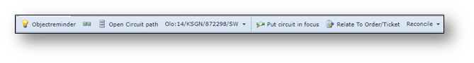
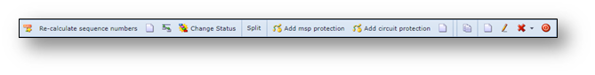
Short explanation of the buttons:
•Objectreminder |
Open the object reminder window |
•NNI |
Open the NNI form |
•Open Circuit Path |
Open the circuit path of the circuit in view |
•Olo |
Open the related OLO-circuit |
•Put circuit in focus |
Put the circuit in view in focus |
•Relate to Order/Ticket |
Relate the circuit in view to the Order/Ticket in focus |
•Reconcile |
Perform reconcile actions on the circuit |
•Re-calculate sequence numbers |
Recalculate the sequence numbers of any ports and carriers of this circuit |
•Duplicate |
Duplicate the circuit in view |
•Find all subs |
Find all sub connections, through multiple layers |
•Change status |
Change the status of the circuit |
•Split |
Split the circuit |
•Add msp protection |
Add MSP protection |
•Add circuit protection |
Add circuit protection |
•Merge |
Merge the circuit with another circuit |
•Copy |
Copies the Circuitname to the clipboard |
•New |
Create a new circuit |
•Edit |
Edit the circuit details |
•Delete |
Delete the circuit |
•Close form |
Close the Circuit form |

Create new circuit
There are several ways creating a new circuit. Some are explained below.
1.Via Circuit form, new button
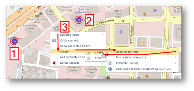
2.Via Network Map – click two nodes, one by one, with left mouse click (a red circle appears around the icon),
| then right click in background in network map, choose option, create > Open create form, speed |
(IMS lists the available port speeds).
3.Via right mouse option on a circuitname 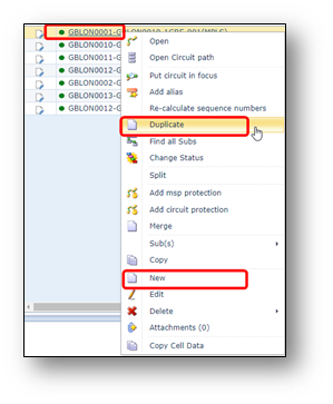
On a circuitname (can be any form), press
right mouse button to get menu.
Choose option “Duplicate” to create a new circuit,
with pre-filled circuit creation form
(same parameters as circuit that was right clicked)
Choose option “New” to get a blank circuit creation
form.
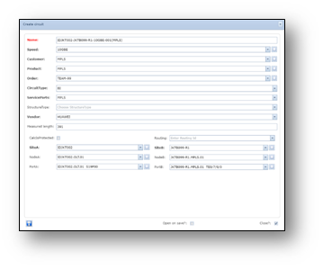
Once the option is chosen, a Circuit Creation pop-up form appears on the screen
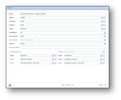
Below a short explanation of the fields:
Name |
Circuitname, will be automatically pre-filled using other fields below. |
Speed |
Speed/Bandwidth of circuit (Circuit type) |
Customer |
Customer or platform name (Circuit Owner) |
Product |
Product Code/Service name related to the circuit |
Order |
Work Order number |
CircuitType |
BI (bi-directional) or UNI (uni-directional) |
Service Parts |
Service Parts/Platform name |
StructureType |
Circuit Structure Type in case a connection has a fixed structure that must be registered. |
Vendor |
Network Vendor |
Measured Length |
Length of connection, measured. |
CalcIsProtected |
Tick box indicating this connection is protected, so that auto routing considers this as a protected route. |
Routing |
An ID field used in case a calculated routing is available using auto routing functionality |
SiteA |
Site name of A end of circuit |
NodeA |
Node name of A end of circuit |
PortA |
Port name of A end of circuit |
SiteB |
Site name of B end of circuit |
NodeB |
Node name of B end of circuit |
PortB |
Port name of B end of circuit |
Manually add circuit to port
If a circuitname is created, without linking the circuit to ports yet, the ports can be added later.
To add the circuit to a port, make sure the circuit is “in focus”.
Below the steps:
1. |
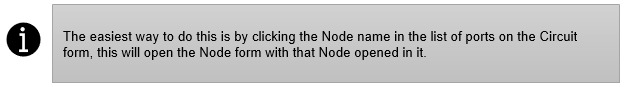
If the Object Reminder is not open, you can click the Lightbulb button. If the Object Reminder does not show the new Circuit in focus, then you must look it up on the Circuit form and click the “Put circuit in focus” button. |
2. |
With the Object Reminder open and the new Circuit in focus go to the Node form. |
3. |
Look up the node where connection should be added to a port. Tip: you can use the history buttons in search area to easily find your node again. |
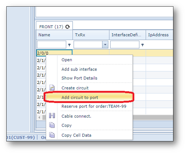
4. |
In the list of ports at the bottom right click on the correct port and select “Add circuit to port”. |
Screenshot: Add circuit to port -example
Create new Circuit with circuit drawer
Another option to create a new circuit is using the circuit drawer in the network map.
Below the steps
1-In Network Map, press button new circuit
2-Click with left mouse button on the first node, select the correct port (you may need to scroll down)
3-Click then with your left mouse button on another node, select a free port with the same port speed
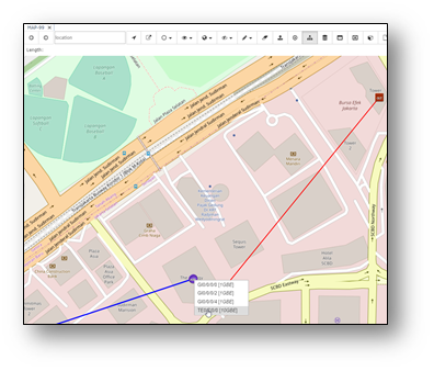
A pop-up window appears, fill in details. Below an example screenshot
4-Press save
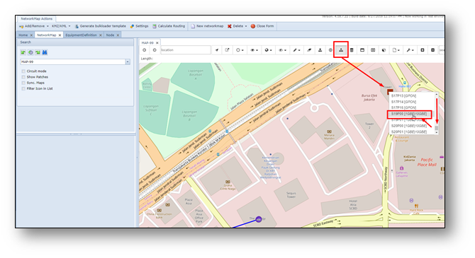
5-Check the Network Map.
The line may not be visible if:
othe settings of the node icons are not set to make your connection type/speed visible.
oThe network You will see that the line is not visible.
This is because the OLT is not set-up for standard showing 10GBE connections on the map.
6-In below example, a new created 10GBE connection was not visible. In order to make the 10GBE visible,
right click on one of the nodes, and choose option: Map settings. A pop-up window appears.
In “PhysicSpeeds” setting, add |10GBE
(note: | = piper symbol) and press save.
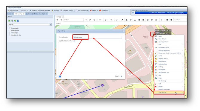
7-Refresh the screen by clicking the binoculars button in search area.
Now you should be able to see the line.
Duplicate circuit
Another way to easily create a new connection is to duplicate an existing circuit/connection.
Normally this is done, when the parameters of the new connection are similar to the existing connection.
Below the steps:
1.Right click on the circuit name in the object reminder or any other grid/table where the circuit name is visible,
choose option “Duplicate”, see example screenshot below.
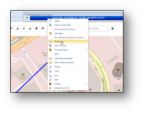
2.Change the parameters that are different
3.Make sure the node/shelf details are filled in correctly (lowest part of the pop-up screen)
4.Update/fill in the port details in case of a physical connection.
5.In case of a logical connection, fill in the node+shelf of the end points, but not the ports.
Add circuit to carrier connection / add sub-connection
To add a sub-connection into a carrier connection, for example a V-LAN into a 1GBE connection,
or 2MB into a VC4 connection, make sure the sub-connection is “in focus”.
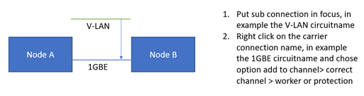
Example screenshot:
Update status of connection
To change the status of a connection, right click on the connection name and select change status.
Select the new status.
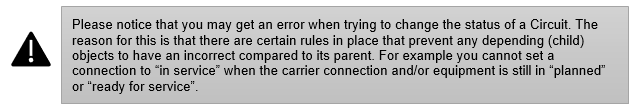
IMS will check if this status change is allowed. If not, an error message will appear at the bottom of the screen.
Migrate a Circuit
When a connection/circuit needs to be changed (other ports or carrier/channel relations) when the connection
is “in service”, the connection needs to be “migrated”.
Below the steps:
1.Lookup the circuit to be migrated (e.g. via search in connection form or via object reminder)
2.Change the status to MI via right mouse menu, change status > MI.
3.Set connection in focus.
4.Change ports:
a.Go to the node form and open the node where the ports must be removed
b. Right click the old port name and select “Reserve for cease”.
c. Open the node where the connection is going to be migrated. This can be the same node
if the connection stays on the same node.
d. Right click the new port name and select “Add circuit to port”.
e. Go back to the Circuit form and refresh the Circuit by clicking the Search button.
You will notice that the ports tab has been replaced by 2 new tabs, Actual Ports and Future Ports.
5.Change carriers
a. Go to the connection form and open the “carriers” tab
b. Right click the old channel from field and select “Reserve for ceasure”.
c. Open the new carrier connection where the connection is going to be migrated.
This can be done in the connection form, but can also be done via the Network Map or
any other form where the new carrier connection name is visible.
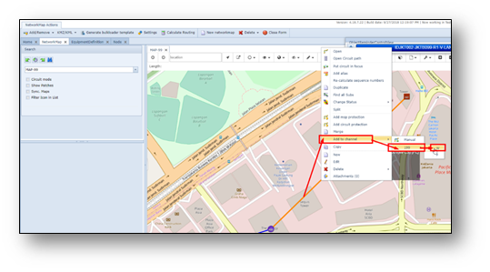
d. Right click on the new carrier circuit name and select “Add to channel” >
<select the correct channel>. In case of V-LANs this must be the VLAN-IDs.
e. Go back to the sub connection in connection form and refresh the Circuit by clicking
the Search button or just refresh the carrier tab.
6.If everything looks fine and migration should already be reflected/completed in IMS then change the
status of the Circuit to IS to execute the migration.
The status change MI (migration) > IS (in service) can also be done in the future in case the migration
activities outside are done in the future.