A floorplan framework is automatically assigned to a Site instance when the Site is created, albeit an empty framework. This can be seen in the Floorplan tab.
Creating a Floorplan actually means enhancing the basic default Floorplan framework - notice the single Floorplan cell in the screenshot below.
The grey rectangles become the headers for the columns and rows (X and Y axis labels). The feint background grid lines can be enabled or disabled, when enabled, they help to better locate room equipment and general items on the Floorplan.
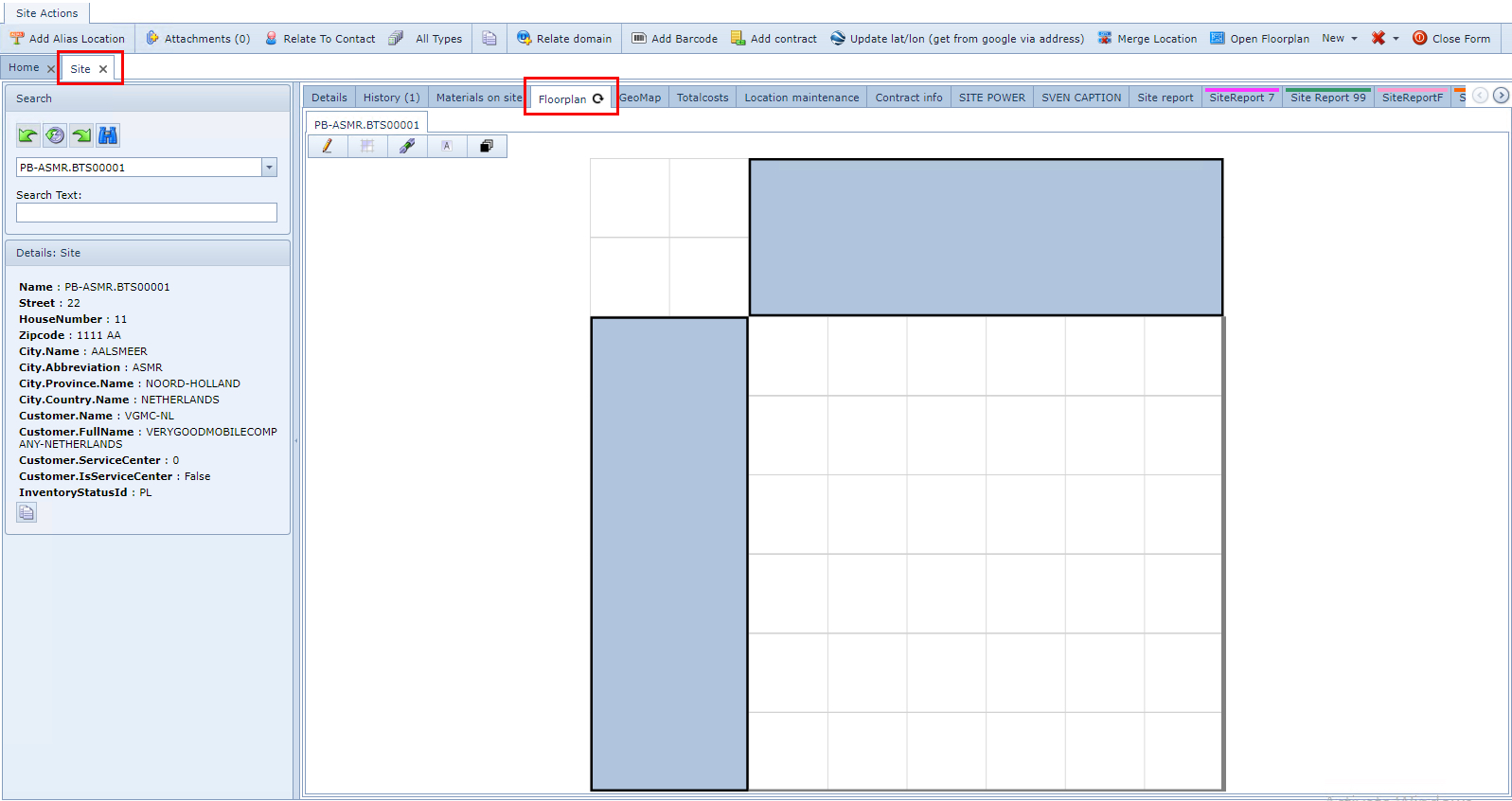
To access a Floorplan:
There are several ways to access a Floorplan.
From the required Site form:
Note: From this point, an existing Floorplan can be modified or enhanced only
▪From the Site Actions button bar, select the Open Floorplan option which will open up the Floorplan object form with the related Site references ... or ...
▪From the row of tabs in the Site form, select the tab called Floorplan, which will display that Site's current Floorplan
From the Floorplan object:
Note: From this point a default or existing Floorplan can be created and modified i.e., number of columns and rows, and the tile's sizes
▪From the IMS Main Menu, select the Site object, and in the dropdown list provided select the Floorplan option, which opens up a blank Floorplan form
▪From the Search area, locate the required Site instance, which open us that Site's Floorplan details
Creating and Designing a Floorplan
From the Floorplan object's Details area:
▪Determine the number of rows and columns that will represent the Floorplan (room) by completing the XAxisLabel and YAxisLabel fields
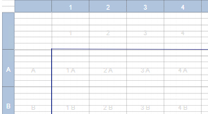
Each label character must be separated by a Pipe symbol | per grid square or tile.
If the first and/or last characters are the Pipe symbols then a blank grid square will be part of the design, as shown in the screenshot below - i.e., left of grid square number 1 and above grid square letter A
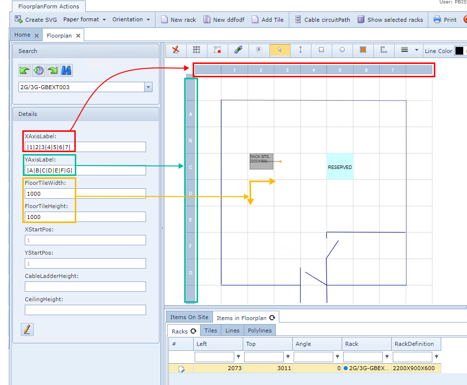
▪Determine the size of the grid squares to be used in the FloorTileWidth and FloorTileHeight fields. These a numeric values that represent the measurement format to be used globally in the company i.e., inches, centimetres, millimetres, etc.
The next steps involve creating/designing the floor layout with Floorplan objects.
•Locate and select the Edit icon - pencil - located at the top left corner of the Floorplan layout area's button bar.
![]()
This reveals further feature icons in the button bar.
![]()
Edit |
Indicates that Edit mode is active or inactive |
Grid |
Places a feint horizontal grid on the background of the Floorplan |
Snap to grid |
Ensures that objects placed in the Floorplan are arranged against the grid - minimal alignment might be noticed. |
Show Cable Trays |
Display Cable Trays in the Floorplan |
Show Tile Labels |
Displays each tile's location label on the Floorplan in a grid configuration - set by the IMS system
|
Arrow |
Selector arrow for choosing objects on the Floorplan |
Line |
Straight line drawing tool i.e., wall perimeter, door angle, etc. |
Rectangle |
Rectangle drawing tool i.e. table, printer desk, etc. |
Elipse |
Circular drawing tool |
Polygon |
Many sided object drawing tool i.e. odd shaped inner room or corner of building |
Polyline |
Create a line that is angular in places i.e. a divider wall with several angled sections, but drawn as one continuous line - left click per line section, double left click to finish |
Line Thickness |
Scaling display thickness option for lines |
Line Color |
Chose a color for a given object; line, polygon, polyline, etc |
Fill Color |
Drawing polygon, rectangle, or elipse shapes can be filled in with colors |
Opacity |
Fill color opacity in percentage, for drawn objects like rectangle, elipse, polygon, etc. |
Save |
Save the work carried out so far |
To Front |
For drawn shapes on the floorplan that overlap, To Front brings the highlighted shape i.e., Elipse on top of any other overlapped shape |
▪Construct the Floorplan using the above features
▪Click on the Save icon in the Upper Right of the button bar, when finished
Other Floorplan enhancements can be applied to individual tiles.
Tile Options
When a tile is right clicked, it provides 3 options as shown in the next screenshot.

NOTE: In the Floorplan Details area window, Tabs of information and object properties details are provided. From these, modifications can be carried out i.e., changing colors and comments as shown in the above screenshot
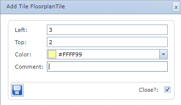
Add Tile
Adds a color to the tile
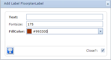
Add Label
This is different to a Comment as in the Add Tile option
No color is added to the tile as a whole, this is a simple label
The Fill Color is the color of the text added
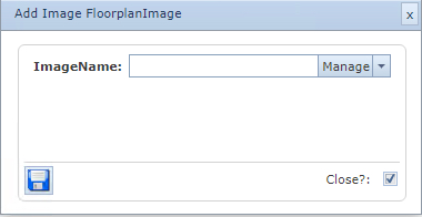
Add Image
If any image files are added to the IMS Server Floorplan then these can be selected and placed accordingly.