From the Network Map Actions button bar select the New NetworkMap icon to open the New NetworkMap popup window.
All mandatory fields are required.
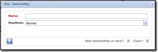
Give the map a name in the Name field.
Select Normal or LoadbyExtend in the MapMode dropdown list.
When creating a new network map there is a choice of two types; Normal and Load by Extend and these represent two different approaches in using this module.
NORMAL
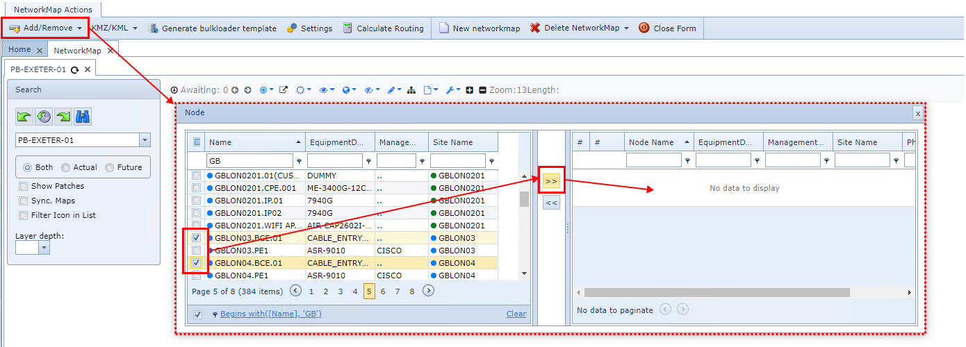
In this mode you have to add the required specific NMS object instances of Nodes or DDFs/ODFs through the Add/Remove option on the Network Map actions button bar - once a map has been created or selected. Be aware that any new Nodes or DDFs/ODFs, from this point on, will not automatically appear on your new map, you have to add these manually.
|
This is not the case, however, for Nodes, DDFs/ODFs, and Circuits created directly using the network map, as these are automatically added. For Circuits, the source and destination nodes must be on the map and the Circuit's speed must be set up to show on the map by selecting the IsGeo check box in the Speed's form.
|
Maps of Map Mode type Normal only, can be created by adding one or more other Map instances already created. This is achieved by selecting the Add/Remove button in the the NetworkMap Actions button bar the Map option in the dropdown list

LOADBYEXTEND
For this mode instead of adding specific elements, you add Sites, Nodes, DdfOdf, and Circuits by selecting their required definitions or types and their zoom levels. This will load all existing instances with the selected types or definitions - there is no way to filter out or add in just specific ones.
The way to add elements to the map is through the Settings option on the Network Map actions button bar once you have created or selected a network map - see the screenshot below. Then in the popup window provided choose the appropriate tabs and select their appropriate IMS Object types and definitions as well as their map Zoom levels - for example, clicking on 7 through 14 to make the item visible when zooming is greater than 6 but less than 15.
The available tabs for IMS Object types and definitions are:
▪Site Types
▪Equipment Types
▪DDF/ODF Definitions
▪Circuit Settings

Circuit Settings
For Circuit Settings, a line for each Zoom level is required for each speed instance. These have to be manually inserted by clicking on the New icon, circled in the screenshot below.
The Color option field can represent the actual circuit's status as it is in the IMS database, fill in this field with CIRCUIT.STATUS, or type in the name of a color i.e. PURPLE.
The Stroke field represents the thickness of the line drawn on the map representing this Circuit.

The choice of Map Mode will therefore depend on whether you require a very specific set of IMS objects (manually selected in the first place) or all IMS Objects of a given type.
The zoom levels can further help display or hide IMS objects - especially useful if there are too many items to display in a small map area - i.e. for a given Equipment Type containing hundreds of items, only show these at zoom levels 23 to 25.