The DDF/ODF form is where patch panels, DDF’s, ODF’s and splice boxes are registered.
Open the DDF/ODF form
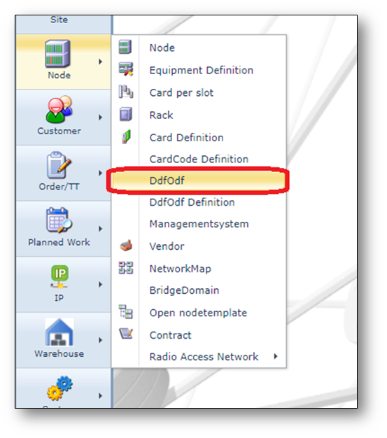
To open the DDF/ODF form, use the node menu option on the left.
Find DDF/ODF/PP/Splice box
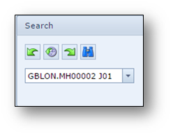
To find an existing DDF, ODF, Patch Panel or Splice box, use the pull down field in the search area
on the left of the screen.
The search starts with the location/site name and then the DDF/ODF name.
Details in the DDF/ODF form
The DDF/ODF form exists of multiple areas of information, see screenshot below.
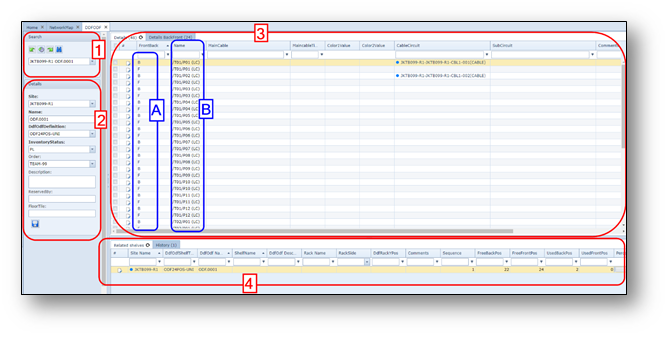
1-Search area
2-DDF/ODF/PP general details.
3-DDF/ODF/PP position details, divided into 2 or 3 tabs.
a. |
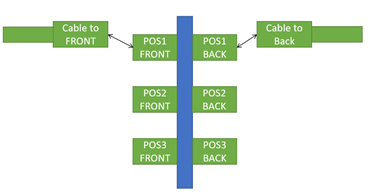
The first tab page provides information about all patch positions of the patch panel/DDF/ODF in one grid/table. The front and back positions are separate rows (section A highlights F=Front; B = Back side, section B mentions the patch position).
The second tab page provides information about all patch positions of the patch panel/DDF/ODF in one grid/table but one row has information about the back AND front position.
The left side of the table contains information about the BACK side, the right side of the FRONT side.
|
b. |
A third tab “Rack” will be visible in case the ODF is placed into a rack/cabinet |
4-The lowest part of the screen exists of some more tab pages:
Related shelves |
provides a list of other shelves of the same DDF/ODF/PP. |
History |
list of historical action related to this DDF/ODF/PP. |
DDF/ODF Button bar
Once a DDF/ODF/PP/Splicebox is opened, a button bar is visible
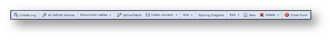
A short explanation from left to right:
Create svg |
Create SVG-file of the DDF/ODF layout |
All ddfodf shelves |
Show all DDF’s and ODF’s in a list |
Disconnect cables |
Disconnect cables from the DDF/ODF |
Splice/Patch |
Open the fiber cable splice window |
Cable connect |
Connect cables to the DDF/ODF |
Site |
Perform Site actions directly from the DDF/ODF form |
Splicing Diagram |
Show a splicing diagram of fiber cables |
Edit |
Change the DDF/ODF name or definition |
New |
Create a new DDF/ODF |
Delete |
Delete the DDF/ODF |
Close Form |
Close the DDF/ODF form |
Create DDF/ODF/PP or Splicebox
To create a new DDF/ODF/PP/Splicebox press the button “new” in the DDF/ODF form.
A pop-up window appears.
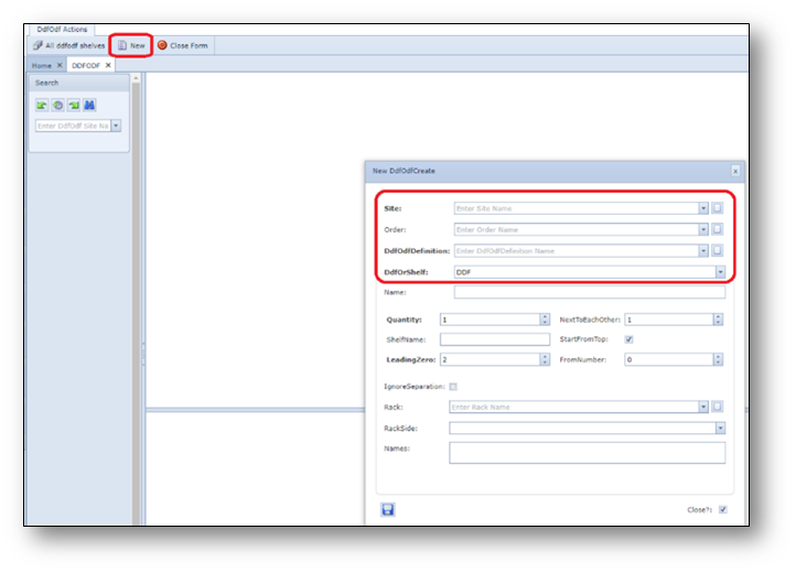
As a minimum the fields in the highlighted section must be filled in.
More information below.
Site |
Site/location name where new DDF/ODF/PP must be installed. |
Order |
Order (work pack) number that is related to this new DDF/ODF/PP |
DdfOdfDefinition |
DDF/ODF/PP type (definition) |
DdfOrShelf |
Indicates if the ODF is one ODF shelf (option: DDF) or that the ODF(Shelf) exists of multiple subshelves (option: SHELF) |
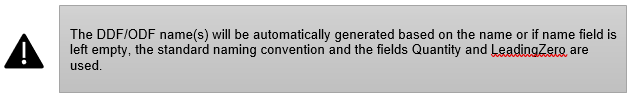
Name |
Name of the DDF/ODF/PP. Will be auto generated if naming convention is set by the IMS administrator. |
Quantity |
Number of shelves |
Shelf name |
Name of the shelf. |
LeadingZero |
This field indicates how many “leading zeros” must be used in the DDF/ODF/PP shelf name. |
NextToEachOther |
This field indicates how the shelves must be positioned in the rack. It indicated how many shelves are positioned next to each other (horizontal) |
StartFromTop |
This field indicated if the shelves must be placed from top to down or from down to top in the rack. |
FromNumber |
This field is used to identify the first shelf number that must be created. |
IgnoreSeparation |
This field ignores the separation symbol (delimiter) in the DDF/ODF/PP shelfname. Often used when only creating one shelf with a specific name |
Rack |
Rack name where DDF/ODF/PP must be placed in. |
RackSide |
Front or Back side of rack |
Names |
A pre-view of the ODF shelf names to be generated |
Connect DDF/ODF position to an Equipment port
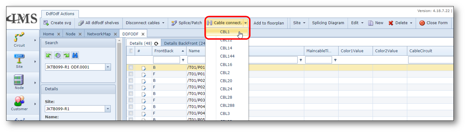
1.Open an existing DDF/ODF with enough free ports.
2.Click the “Cable connect” button and select the “CBL1” option.
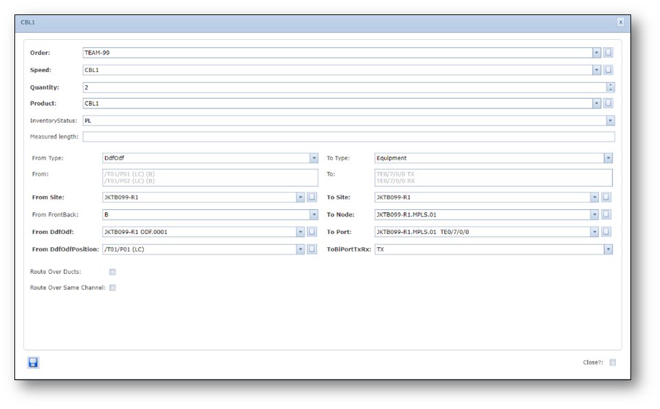
3.Fill in the following details (assumption is start from DDF/ODF and to Equipment (Node)):
Order |
Order number (Automatically filled in when Order is in focus |
Speed |
Cable type, for example CBL1, for a normal patch cable. |
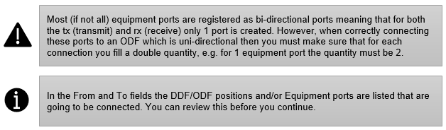
Quantity |
number of cables, for example 2 |
InventoryStatus |
status of the new cables, for example PL, RFS or IS |
From Type |
DdfOdf or Equipment, now assuming start point is DDF/ODF |
From Site |
Site name of DDF/ODF (now assuming start point is DDF/ODF) |
From FrontBack |
B (in case of BACK side) or F (in case of FRONT) side |
From DdfOdf |
select a starting DDF or ODF name |
From DdfOdfPosition |
Starting DDF/ODF position |
To Type |
Equipment of DdfOdf (now assuming B side is Equipment/Node) |
To Site |
nodename |
To Port |
portname to connect to |
Route over ducts |
disabled |
Route over same channel |
disabled |
4.Click the “Save” button to make the cable connections.
Screenshot: Cable connect
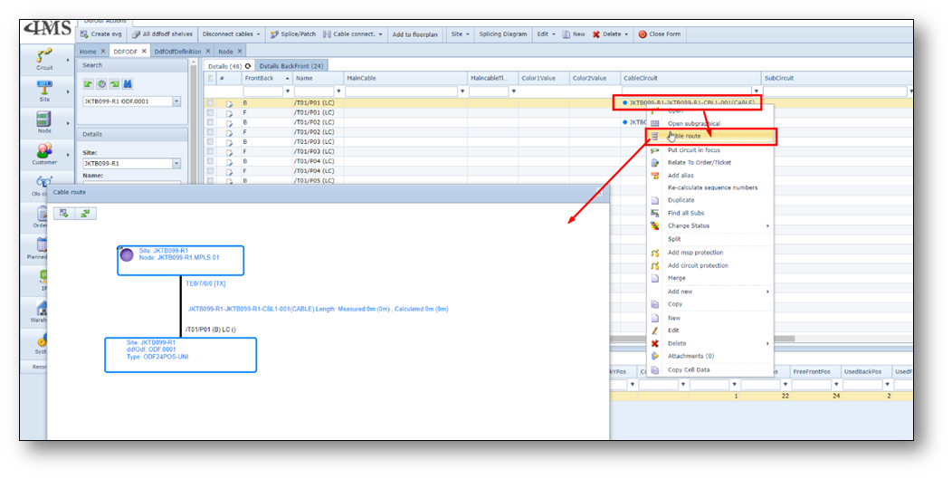
5.The cables are connected now. You can check the cable route from ODF to Equipment.
In the ODF grid, on the Cable circuit name, right click and choose 3rd option “Cable route”
(see screenshot below).