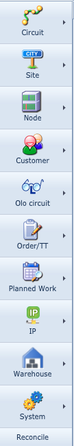
The IMS button bar provides access to all the object forms categorized by network topic. Each button reveals functionality related to its object type.
Selecting any one of these options, opens a form in which to manage the object , i.e., View, Create, Modify, and Delete.
IMS Main Button Bar
|
The screenshot on the left shows all the main features in the IMS system. Over the course of this training, we will cover most of these features, both from a knowledge and practical perspective.
VC4 IMS has, at its core, a relational database holding the data associated with all the network object instances needed to manage and run a successful telecom or network business.
These object models i.e., Customer, Site, Node, are linked together in one way or another. There is also a hierarchy structure which is followed and enforced, for example, an ethernet port cannot be modelled and kept on its own, it must belong to a card object. In turn, this card object must first be associated to a slot, and finally this slot must also be associated with a piece of equipment (node).
|
Circuit
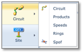
The circuit object represents connectivity. The type of connectivity to be modelled is limitless and can represent the current infrastructure and services provided as well as planning and getting ready for future ones, in line with the business plan.
Circuit |
Connections, circuits, cables, and services |
Products |
Product codes or type of services i.e. [Duct, VLAN, Abis, Fibre144] |
Speeds |
Bandwidth capacity i.e. [vc4-16c, 10GBE, 64Kbps, Lambda] |
Rings |
Aparticular connection topology i.e. [SDH, Sonet, WDM] |
Spof |
Single point of failure - circuit redundancy management |
Site
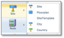
The site object represents location. Some examples of a site object can be a: manhole, building, a geographical area of a city (i.e., a city block), radio pole, BTS, and so on. Sites can be ‘nested’ too, these are subsites.
Site objects are a powerful feature as they contain a vast amount of related data, providing the user with quick and valuable information to hand. As an example, from one site you will find all related circuits, equipment, available ports, contact persons, and so on.
Site |
Main location object as explained in the earlier paragraphs of this topic |
Floorplan |
Provides the user a graphical interface to manage floor space |
Site Template |
A multi-create feature to quickly rollout related equipment, ODF/DDFs, splice boxes, etc., at any given location (you add equipment templates to the site template) |
City |
Contains related city, regional, and provincial details, linked to many other objects like city, site, nodes, circuit, etc |
Country |
Contains country details. A high-level location feature but linked to many other objects like city, site, nodes, circuit, etc |
Node
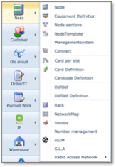
The node object primarily represents equipment. Yet it is more than just equipment and as you see from the above screenshot, it also manages many related network items, like S.L.As., racks, and vendors.
Node |
This as an individual instance of equipment like a router, switch, MUX, dish, or even a monitor |
Equipment Definition |
The Equipment Definition object allows for the creation and subsequent management of all vendor equipment, primarily in this case at the shelf / node level. There are other options to create card and distribution frame definitions, which are mentioned further on. In essence, we ‘define’ the layout of the shelf / node |
Node Sections |
A feature to show the connectivity between two nodes. Information like; current and future (planned) connections, physical and logical, ‘Percentage used”, etc. can be accessed with this feature |
Node Template |
A node based on an existing equipment definition instance can be kept as a template. These templates can then be associated to the Site Template instances. Used to roll out sites with predefined equipment in a cookie cutter fashion. Status is set to planned and a work order usually associated with it |
Management System |
A feature to setup IMS to integrate with other systems, through Application Programming Interfaces (API), i.e.: Network Management Systems (NMS) Element Management Systems (EMS) Alarm Management Systems (AMS) Customer owned applications, etc. |
Contract |
Manage contracts dealing with leased lines or vendor equipment. Conveniently store invoicing and contact details |
Card per slot |
Enforce which cards are allowed in which slots in all your nodes through this feature |
Card Definition |
Define and manage your card types or card blueprints in line with vendor specifications |
Card Code Definition |
Allows for the identification of cards bearing similar names but possess variations, like 10GBE and 1GBE interfaces. Card Code Definitions are closely linked with Card Definitions. |
DDFODF |
Instances of Digital and Optical Distribution Frames as well as patch panels |
DDFODF Definition |
Similar to Equipment Definition but tailored to the nature of distribution frames i.e., front and back connectivity aspects |
Rack |
Allows for the modelling of containers/cabinets that house equipment and where details of which can be stored. A handy graphical representation is given, as well as showing up in Floor Plans |
Network Map |
This is a powerful and very useful IMS tool to not only view network objects but also manage them in a map layout. You can create new maps with options such as a blank or geographical backgrounds, provide distance and cluster details, as well as importing or exporting maps in KMZ or KML formats |
Vendor |
This object stores your vendors information i.e., OLO or equipment. From here you can link to other object like equipment definitions and nodes |
Number Management |
Telephone Number management feature for tracking ranges of numbers. |
eSIM |
Store and manage SIM card information i.e., Euiccid, Eum ID, Platform version, etc |
SLA |
Create and manage SLAs, which will then be referred by other objects like contracts, and vendors. SLAs hold details like severity levels and their response times |
Radio Access Network |
This module is designed to create and manage mobile networks, from RF, antennas, poles, and towers, etc. |
Customer

Customer |
Details of your customers are stored here. You may also access related information such as their location, orders, trouble tickets |
Contact |
Manage all the various contact persons for a given customer |
OLO Circuit
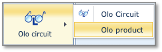
Other Leased-Line Operators
OLO Circuit |
Where all OLO circuit details are stored and managed |
OLO Product |
Define the product type for the OLO circuits i.e., 10GBE Leased Line, 2MB Voice, etc. |
Order/TT
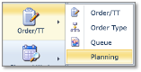
Order/TT |
Create and manage work orders and trouble tickets. Trouble tickets can also be assigned to an order known as a parent order |
Order Type |
A work order is associated with a specific job or purpose, here known as Order Type. For example, a work order might be selected to decommission and remove a router from a site. This ‘decommission and remove’ process could be the Order Type, against which an appropriate set of instructional tasks will have been created |
Queue |
These are repositories for orders and trouble tickets and associated with different departments, typically by role-types i.e., circuit provisioning, network planning, equipment deployment, etc. Department members can sign out and sign in their respective tasks |
Planning |
This tool allows for network administrators to assign and manage work orders (existing or new) to individual users using a handy time-based planner |
Planned Work
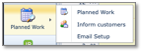
Planned Work |
Network administrators can create and manage work in the future and assign network objects to it that will experience some impact. Objects like equipment and circuits can be assigned |
Inform Customers |
Where the outcome of impact analysis of the planned works can be managed and communicated to customers |
Email Setup |
Where the e-mail templates are managed used for informing customers of planned works |
IP
![]()
Domain |
Network administrators can create and manage work in the future and assign network objects to it that will experience some impact. Objects like equipment and circuits can be assigned |
IP Ranges |
Where the outcome of impact analysis of the planned works can be managed and communicated to customers |
Warehouse
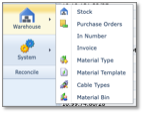
The IMS Warehouse functionality primarily aims to control the movement and storage of materials within a warehouse and process the associated transactions, including receiving, put away, and picking.
Stock |
known as ‘material’ that is recorded and managed in the warehouse. Material can be any asset, not just shelves, racks, and cards i.e., it could also be office chairs, mobile phones, etc. |
Purchase Orders |
Orders of material from the suppliers or vendors |
In Number |
An In Number is created to contain details like amount (budget), currency, etc., and is associated to an invoice |
Invoice |
Contains the data that make up an invoice i.e. Purchase order number the invoice relates to, currency and amount, etc. An invoice report can also be generated in various formats like PDF, CSV, HTML, etc |
Material Type |
general descriptive type of the material i.e., cabinet/frame, cabling, BIRT (testers), etc. |
Material Template |
Useful feature when repetitive ordering of the same groups of materials takes place. Speeds up ordering with fewer clicks of the mouse |
Cable Types |
Register and manage different types of cable i.e., Ethernet CAT 7, Shielded BNC, Multimode Fiber: 850nm and 1300nm, etc. |
Material Bin |
Material that is consigned for selling to third parties or scrapped, are assigned bin numbers |
System
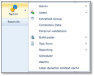
The system button reveals further functionality that is aimed at ‘super users’ or network administrator type users. This section is reserved for network administrative staff with the appropriate privileges.
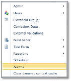
Admin
![]()
The Admin dropdown item contains 3 further items.
Active User Sessions |
This reveals all users currently logged into IMS and are in an active status. It also provides information like the browser being used, session ID, and ‘Active Until’ time frame |
Show All History |
Reveals past user actions where objects have been created, modified, or deleted |
Manage log Files |
System log files can be viewed with this feature. These log files contain error information between the front and backend system |
Users
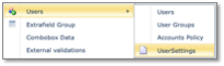
The Users dropdown item contains 4 further items.
Users |
Option to create new IMS users, modify, or delete them |
User Groups |
Manage your user groups and their permissions with this option |
Accounts Policy |
Enforce secure access to the IMS platform for your users. This option sets up user passwords, lockout durations, password hash option, etc. |
User Settings |
|
Extrafield Group
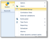
IMS Admin users can create additional tab pages and fields and associate these with existing IMS objects i.e., a new tab of BTS Cell Tower data (fields) can be created on the fly. There is no need for a new IMS version to be rolled out for this.
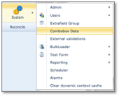
Combobox Data
Drop down boxes can be created allowing you to insert specific values that must be chosen when applied to the IMS object in question. This helps enforce data integrity across your business.
External Validations
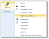
External validations are queries that can be associated to objects in IMS to validate any data that is filled in. This is validation separate from any inbuilt IMS validation i.e., if a business process demands that certain equipment should no longer be considered by users in any of their current work, a validation can be carried out that checks the End of Life (EOL) date on the equipment definition.
BulkLoader
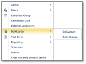
Feature that allows external customer data (spreadsheet) to be loaded into IMS objects
Reporting
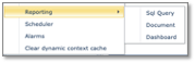
The reporting functionality allows users to create and modify reports in a style and format more of their choosing. These can then be printed or saved in standard formats like PDF, DOCX. Reports can be made using straight SQL, a Designer, Designer Wizard, and a Dashboard module.
Scheduler
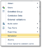
Scheduler is the functionality to automatically schedule reports (sql or document) to be sent to a user or a list if users, via email or ftp.
Alarms
The Alarms module displays in a tabular format incoming network alarms. They are also related to the network element at fault i.e., card, or port. Trouble tickets can also be associated with alarm entries.
Alarm monitoring and display are at their best when linked to external alarm monitoring systems giving near real-time tracking of the network status.
Alarm maps, including street map type, can also be displayed.
Clear dynamic context cache
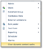
If dynamic objects are defined these are cached in memory, this functionality enables the deletion of the cache so updates can be implemented.
Search area
The search area is present on all forms in IMS and offers an easy and standardized way for navigating through the objects on the forms.
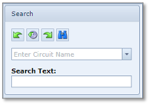
The 4 buttons in the search area provide the following functionality (from left to right)
Previous |
go back to the previously viewed object |
History |
stores the last 20 viewed objects |
Next |
navigate to the next viewed object – provided you have used the Previous button |
Search |
(binoculars): Left click to search what is filled in the Search Text field or right click to clear the screen |
Search Text (field) |
Enter your search string here – partial or complete |
|
Not all forms have this last Search Text field |
Object Status
By default, newly created objects like circuits, nodes, cards, etc. are given the status PL which can be updated to another status manually or by an automatic process.
Below is a list of the statuses used in IMS showing related objects.
Code |
Colour |
Meaning |
Related objects and details |
PL |
blue |
Planned |
This is the default status for new objects in IMS. The PL status is used for the objects: Site, Circuit, OLO Circuit, Node, Shelf, Card, DDF/ODF and RAN objects. Objects with PL status are allowed to be modified. |
RFS |
purple |
Ready For Service |
This status is used for objects to indicate that they are present (installed) in the network but not yet fully operational or carrying live traffic. Like the PL status, objects in this RFS status can be modified. The RFS status is used for the objects: Circuit, OLO Circuit, Node, Shelf, Card, DDF/ODF |
IS |
green |
In Service |
This status is used to indicate that the objects are present and operational, possibly carrying live traffic in the network. Configuration changes are not allowed. The IS status is used for the objects: Site, Circuit, OLO Circuit, Node, Shelf, Card, DDF/ODF. |
MI |
orange |
Migration |
This status is used for the Circuit object only and is used to plan a change or migration of the circuit, for example a change in the circuit route or change of (equipment) port. This status offers the functionality to keep a view on the current/actual state of the circuit and the newly planned/future state of the circuit next to each other. |
RFC |
brown |
Ready For Cease |
This status is used to indicate that the objects are still present in the network and operational, possibly carrying live traffic, but that they are planned to be removed. Changes are not allowed. The RFC status is used for the objects: Circuit, OLO Circuit, Node, Shelf, Card, DDF/ODF. |
OOS |
red |
Out Of Service |
This status is used to indicate that the objects are no longer present or active in the network and the related date disconnected and saved in the history. The OOS status is used for the objects: Site, Circuit, OLO Circuit, Node, Shelf, Card, DDF/ODF. |
Object History
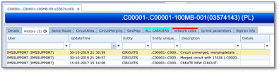
Almost all objects in IMS have a history which keeps tracks of the object’s lifecycle throughout IMS and all changes are logged and can be seen in its history tab.