The Network Map form allows users to manage the inventory in graphical and/or geographical way.
The form also offers a set of functions that allows the creation of the most used objects like Sites,
Nodes and Circuits directly on this form.
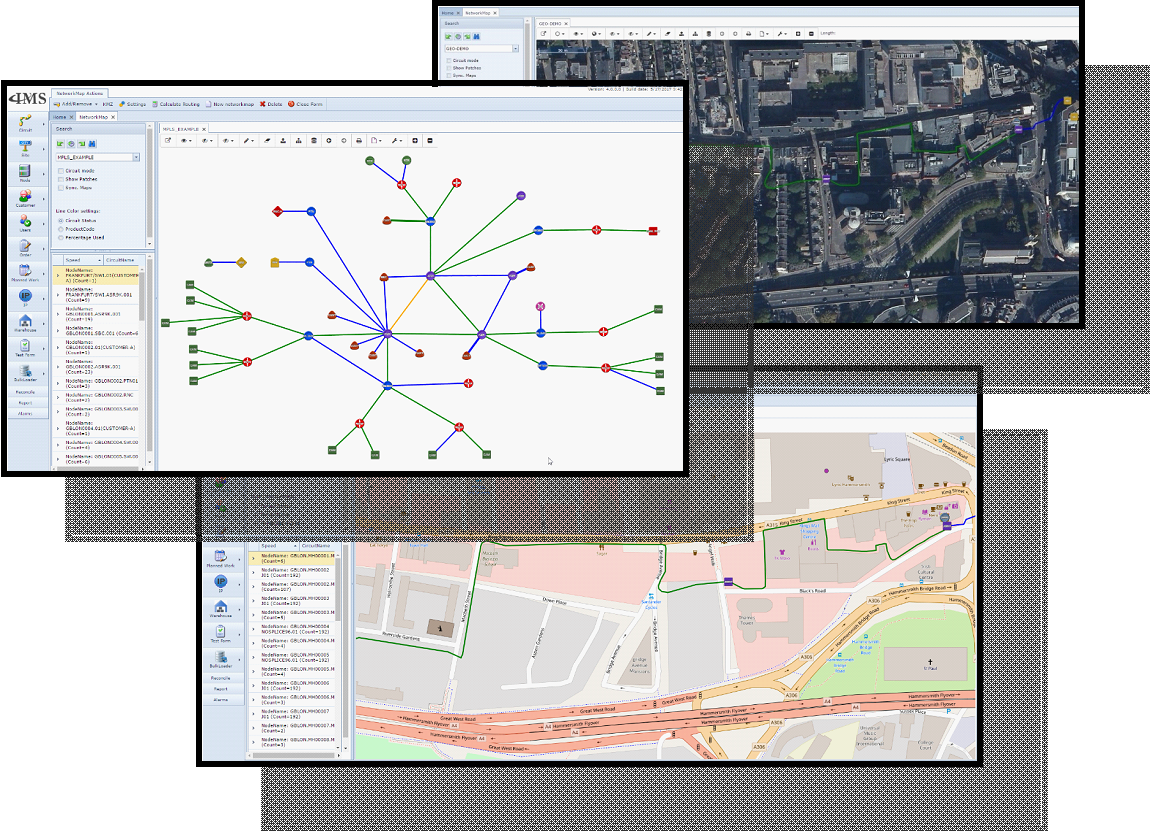
Screenshots: examples of Network Maps, graphical and geographical.
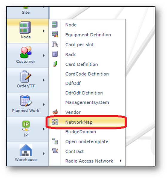
Open Network Map Form
The Network Map Form can be opened via the “Node” menu on the left of the screen.
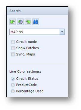
Find Network Map
Existing Network Maps can be found using the search field on the left.
Move Network Map
To move the Network Map (content)
1.Move the map by clicking and holding the background of the map and moving your mouse.
2.You can zoom in and out with your mouse wheel or by using the + and – buttons.
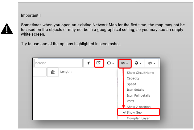
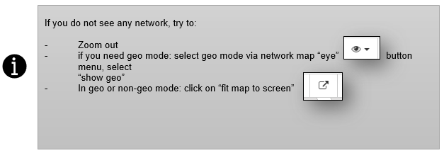
3.To view the map in geo mode, Enable the Show Geo option under the Map display options.
Network Map Actions button bar
Once the Network Map is opened, the following button bar is available
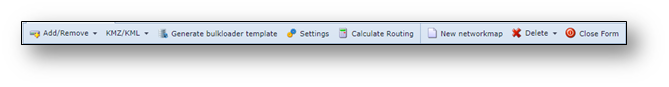
Buttons from left to right:
•Add/Remove |
Add or remove objects from the network map |
•KMZ/KML |
Function to import or export KMZ- or KML-files |
•Generate bulkloader template |
Generates a bulkloader template of the network map |
•Settings |
Change the name of the network map |
•Calculate Routing |
Function for automatic routing between 2 nodes |
•New networkmap |
Create a new network map |
•Delete |
Delete the network map |
•Close Form |
Close the Network Map form |
Network Map in-map button bar
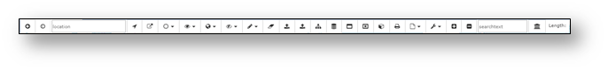
Here a brief explanation of the buttons found at the top of the network map from left to right:
•Previous map position
•Next map position
•Search field, address, city, etc. using the map provider
•Go to current location
•Fit map to screen
•Set the map transparency
•Map display options
•Choose map provider
•Show/hide Icon and Line types
•Choose draw option
•Clear draw buffer
•Save draw buffer or measuring, for creating multiple sites or polygons
•Select points for new sites, for creating multiple sites and automatically connecting them to
the existing network (nearest point)
•Create circuit
•Reload local database
•Create extend
•Remove extend
•Create Autocad document
•Print to PDF
•Choose paper format
•Choose DPI setting
•Zoom in
•Zoom out
•Search field
•Search point of interest
•Displays the length of a line measure
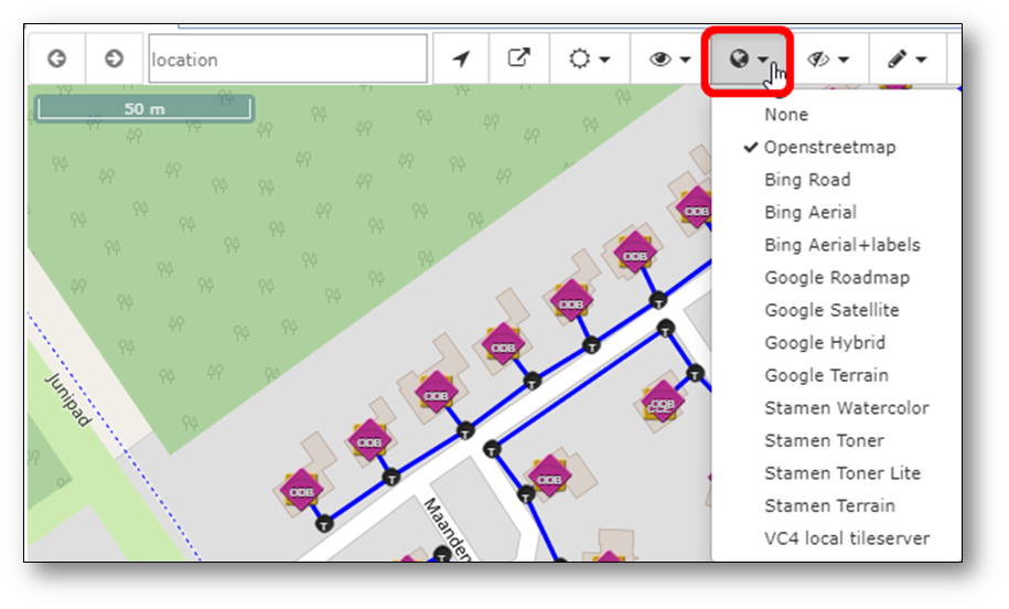
Change Network Map backgound map type
There are different geo background provider options (if configured for your organization).
To change map type, use the option as per screenshot:
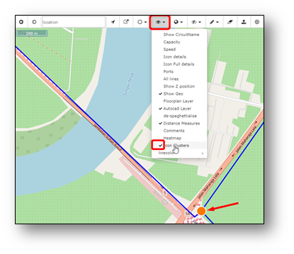
Icon clusters
In the GEO-mode, equipment on the same location, can be drawn on top of each other
(icon clusters disabled) or presented as an orange dot grouping the equipment together.
Icon clusters enabled
To enable the icon clusters, select the option in menu as per below screenshot.
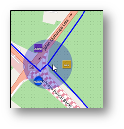
When you move the mouse arrow on the orange dot, the dot will “open” and show all the equipment
in a circle around the center, see example below:
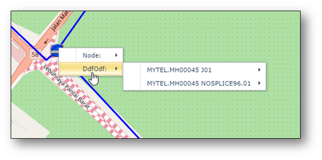
Icon clusters disabled.
When the icon cluster option is not selected, the equipment icons are drawn on top of each other
and when right clicking on it, IMS will show the different equipment names via the right mouse menu
List related connectivity of object
In the Network Map, in geo or non-geo mode, when clicking on an object (node, DDF/ODF, circuit),
IMS will list all traffic (and sub-traffic) in a grid on the right side of the screen.
For example:
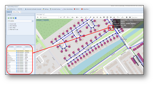
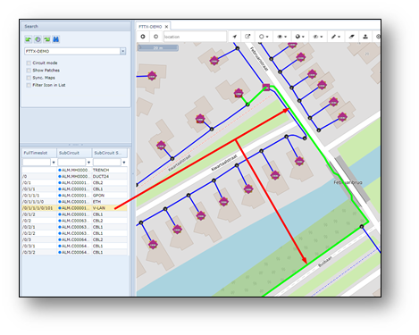
High-light connection
After clicking on an object, the list of related connections will be listed in the grid on the left side
of the screen. When clicking on a circuitname in that grid, the connection will be highlighted on the
network map.
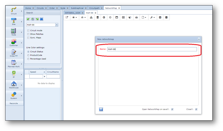
Create a new Network Map
To create a new network Map, click the “New networkmap” button on the NetworkMap Actions bar.
A pop-up window appears.
Fill in the name of the new network map and press save.
Add (existing) objects to the network map.
To add (existing) objects to the network map, use the button menu Add/Remove, see screenshot below.
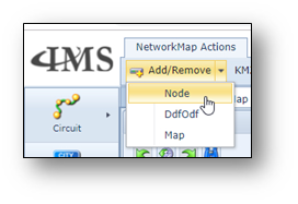
For example, to add one or multiple nodes, use the Node option.
A pop-up window appears.
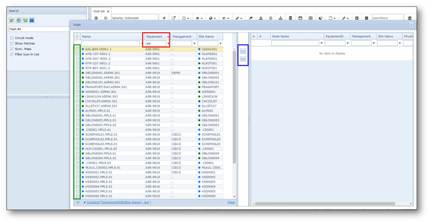
The left side of the pop-up window lists all objects that are available and not yet in the Network Map.
The right side lists all objects that are already in the Network Map.
To find an object, find it in the list, and/or use the filter options (see example filter highlighted in red in
screenshot).
To add one or multiple objects, use the tickbox on the left (see highlighted in green) and then
press >> button (see highlighted in blue).
Objects selected will move from left to right.
When finished, close the form and refresh the network map, by using the binoculars button in the
search field area.
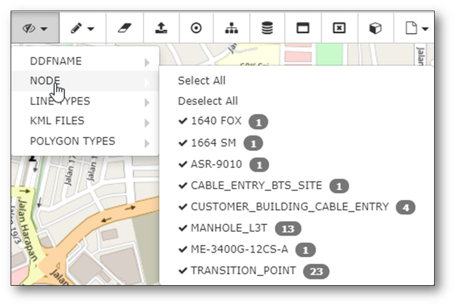
Make objects visible/invisible in the Network Map.
Via the “icon and line type” menu, users can “make visible” or “make invisible” objects in the Network Map.
For example, when creating connections between nodes, it is easier if there are no DDF/ODFs visible on
the screen, while creating cable connections, it is easier to deselect all (active) nodes.
Enabling/disabling can be done for DDF/ODFs, Nodes, Line types, KML files and Polygon types.
Below example for node types.