Scenario: MPLS network aggregating VLANS at the edge.
In order to use the Sub Node feature, preliminary work will have had to take place, namely setting up the definitions. It is not the intention to describe in this document how to create equipment definitions, but rather remind the user that these must exist.
The following steps would be followed by a member of staff who has an appropriate IMS Network Administrator role.
1 |
An equipment definition is required for the parent node and the Sub Nodes. This defines aspects of the technology that will be modelled, in this case MPLS / VLANS, etc. |
In our example, 3 Equipment Definitions will be required.
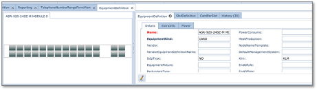
a)ASR-920 type of router (parent)
b)BRIDGEDOMAIN (Sub Node - virtual)
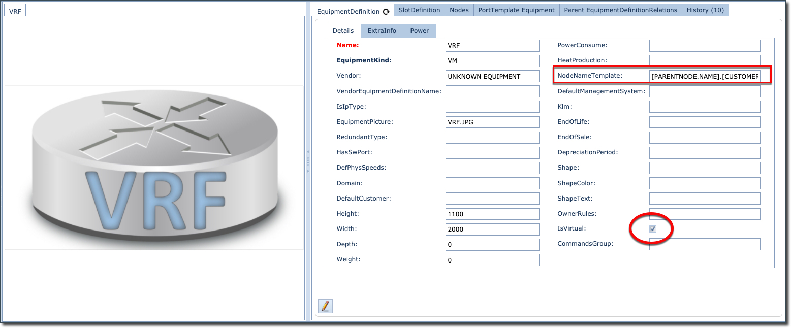
c)VRF (Sub Node - virtual)
|
It is necessary that both Sub Node definitions have the IsVirtual tick box enabled (shown in the next diagram). Without it, you will be unable to select any Sub Node definition when adding sub equipment definitions to the parent equipment definition i.e., creating the parent child relationships - as will be described in the next section. |
2 |
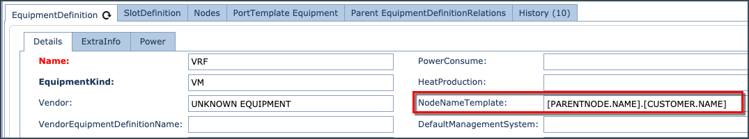
Include a NodeNameTemplate for a name generator, in this case we have used the Parent Name + Customer name |
3 |
Slot and Card definitions will also be required for the parent node. (In our example no slot/cards will be necessary for the Sub Nodes) |
o24-PORT GIG &
o4-PORT TEN GIG SFP ETHERNET INTERFACE
4 |
For the purpose of completeness, slot and card definitions will be needed for elements like Power and Fan modules. |
The next step is to relate these 3 equipment definitions.