As stated earlier, it is not the intention in this document to explain in detail how to model MPLS architecture in IMS, however in this next section we will see how one MPLS type service has been related to the Sub Nodes.
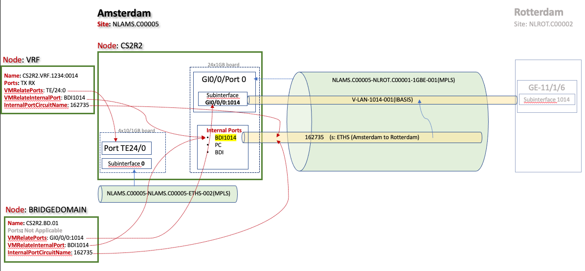
The following diagram shows how the MPLS elements are modelled and relate in IMS
Once the Node and Sub Node infrastructure is in place, then circuits of various kind can now be added to IMS to complete the MPLS modelled network.
It will be the case that different end user requirements will drive and maybe adopt only certain aspects of their MPLS network according to; architecture, vendor equipment, available features offered, customer offerings, etc.
The following network diagram shows the relationships between IMS and MPLS modelled objects.
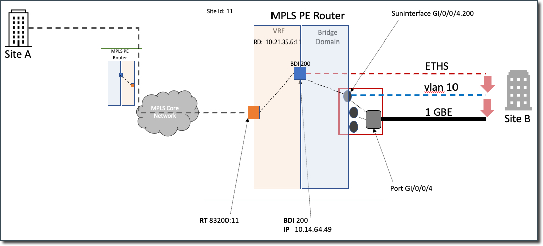
Packet Edge Router and associations
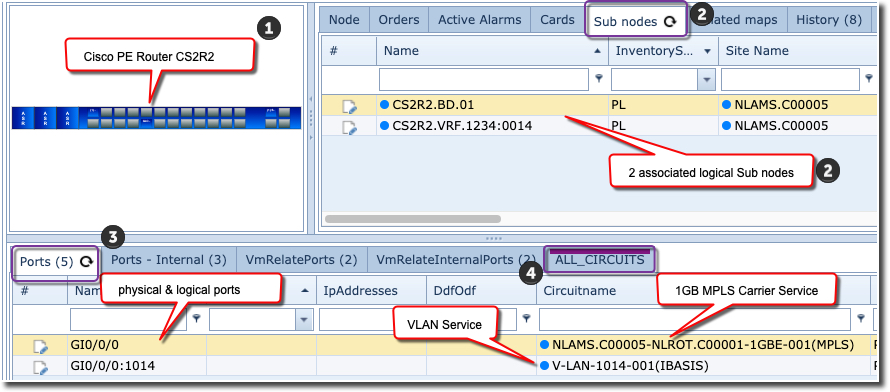
The following diagram depicts the following elements:
Cisco Router (1)
Sub Nodes (2)
Ports (3)
Circuits (4)
Furthermore, if we click on the Ports – Internal tab we see the following associations
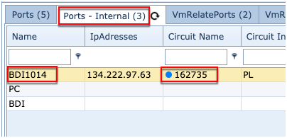
In this case, the Ethernet Service [162735] terminates on one of these internal ports labelled with its BGP identifier [BDI1014]
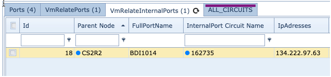
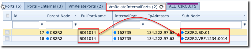
The VmRelateInternalPorts tab on the PE Router, also reveals its associations to the 2 Sub Nodes.
The important thing to remember here is that this tab is explaining that there is a relationship between the configuration on the main equipment (CS2R2) and this virtual machine (Vm).
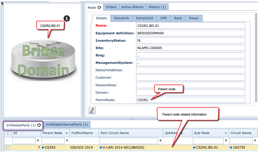
Bridgedomain and associations
The Bridgedomain Sub Node is a virtual device, yet circuits and devices can still be associated to it. As in the next figure we can see from the VmRelatePorts tab.
In this example there is only one circuit, yet in reality there could be many more. Remember that this is a relation to the physical port of the main equipment.
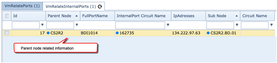
The VmRelateInternalPorts tab reveals its parent node’s internal port information that are related to this virtual machine, in this case the Ethernet Service name, IP address, and the circuit of the parent node’s internal port.
VRF and associations
The final component to this model is the Virtual Route Forwarding (VRF) Sub Node.
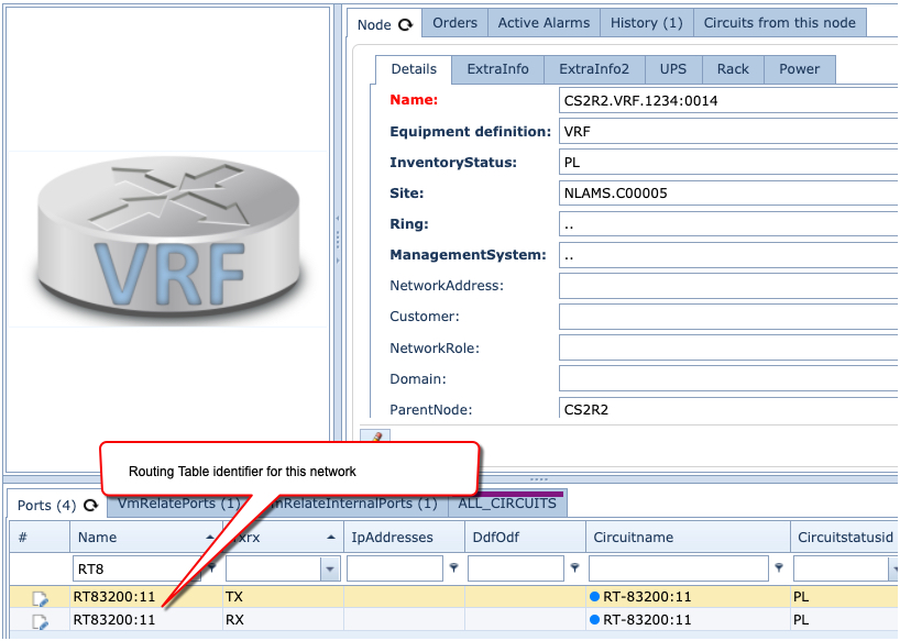
Virtual ports can be assigned to the VRF, in this case a TX and RX is representational only, and the RT identifier associated to them (i.e. the export/import RT.
A new circuit is created with the RT information as well, and then assigned to the VRF’s TX & RX ports for completion. This circuit, although not a real circuit in the normal sense, serves the purpose in IMS to relate the RT to the distinct VRF instances that are part of a Hub/Spoke or Full Mesh network for this particular customer.
As with the BRIDGEDOMAIN, the VmRelateInternalPorts and VmRelatePorts tabs in the VRF Sub Node reveals its parent node’s (internal) port information that are related to this virtual machine, in this case the Ethernet Service name, IP address, and the circuit of the parent node’s (internal) port.