Before uploading Shapefiles into a Network Map first ensure that the appropriate Permission and Setting has been established as follows:
Shapefile Permission and Setting
Permission setup
In order to upload Shapefiles, a User Group's Permission to do so must first be enabled. This is achieved by accessing the UserGroupPermission Tab as follows:
From the IMS Main Menu:
▪Select System | Users | User Groups
This opens up the UserGroup Form
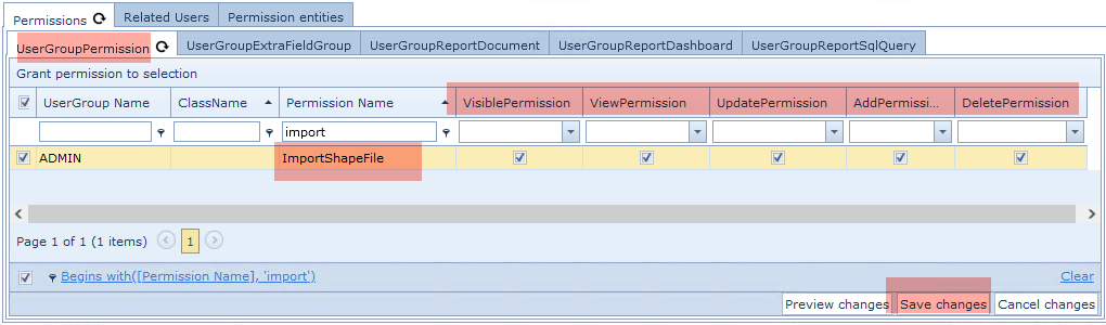
From the Permissions Tab and then in its nested Tab called UserGroupPermission ...
▪Type in import in the Permission Name column filter field and press the Enter/Return key - you should see the Permission Names listed as in the above screen shot
▪Ensure that the Permission Name option called ImporShapeFile is enabled in the respective permission columns, right of the Permission Name column
▪Click on the Save Changes option button in the lower right corner
Setting setup
From the IMS Main Menu:
▪Select System | Users | UserSettings
This opens up the UserSettings Form
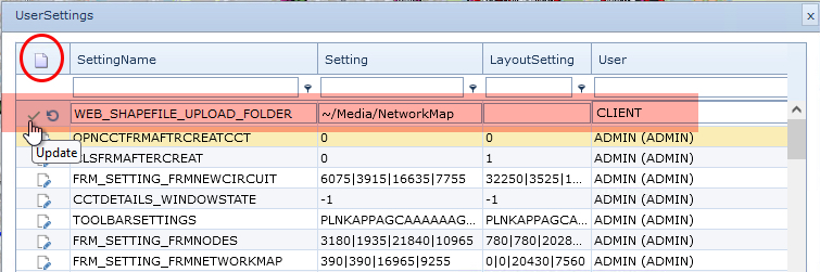
▪Click on the New option (Paper Icon)
Type in the following:
oIn the SettingName field: WEB_SHAPEFILE_UPLOAD_FOLDER
oIn the Setting field: ~/Media/NetworkMap [this is the Media component on the server and Network Map folder]
oIn the User field: CLIENT [enabling it globally]
▪Click on the green Tick icon to Save the new Setting
Enable Shapefiles on Network Map
The next step is to enable the Network Map to reveal details from a Shapefile
From the Network Map's menu bar:
▪Click on the Show Icon and Line Types option (eye with a slash icon)
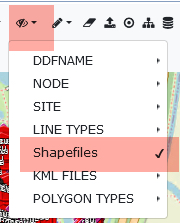
▪From the drop down list of option select Shapefile to enable Shapefiles
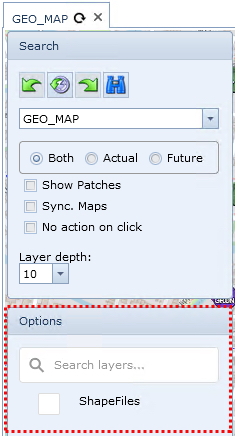
This will reveal the Options panel under the Search section, left of the Network Map form as shown below in the red dotted square.
Notice the Search field for locating any existing Shapefile folders and the default ShapeFiles element indicating the top level for all folders. All Shapefile folders will be nested under this default element.
Create a new folder to hold the Shapefiles
▪Right Click on the ShapeFiles top level element - revealing the Add folder option
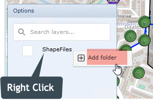
▪Click o the Add folder option - revealing the Add folder popup window
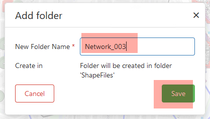
▪give the new folder a name by filling in the New Folder Name field
▪Click on the Save button
Drag & Drop or Delete Shapefiles
The following steps are required to upload Shapefiles into the appropriate folder:
oIt is assumed that the required shape files are available ready for uploading them into IMS oZip files that contain one .shp file can be dragged and dropped into folders |
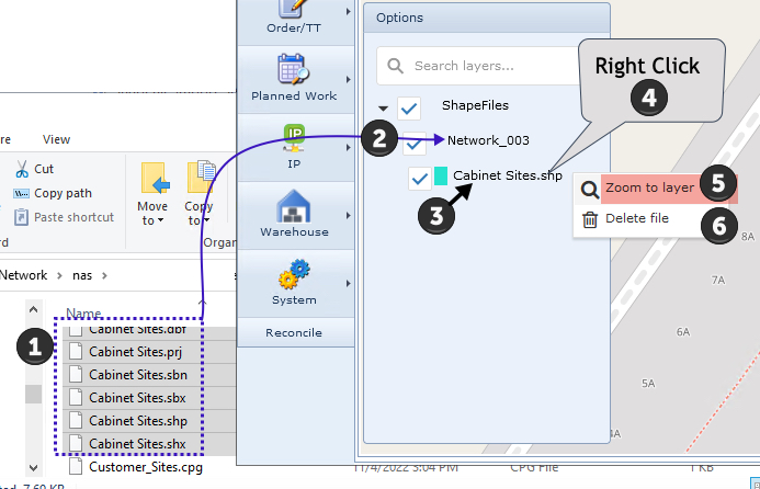
1 |
Locate Shapefiles of like type i.e., Cabinet Sites in this example, Highlight them |
2 |
Drag and drop them onto the newly created folder i.e., Network_003 in this example
|
3 |
A new file is created using the Shapefile group name, under the parent folder |
4 |
Right Click on this new file This will open up a drop down list with two further options |
5 |
Click on Zoom to layer to reveal all the newly uploaded Shapefile items on the Network Map |
6 |
Click on Delete file when a folder or file is no longer required |
Repeat steps 1 & 2 to drag and drop more files that represent the different layers of network items onto the Network Map - in this example Cabinet and Customer sites |
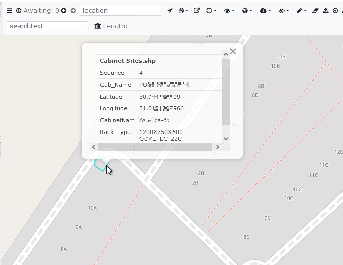
In the next screen shot two layers containing two different network elements are represented by the two files, both are ticked/enabled so both network element types are displayed. Conversely, de-selecting one or more will hide those elements from view

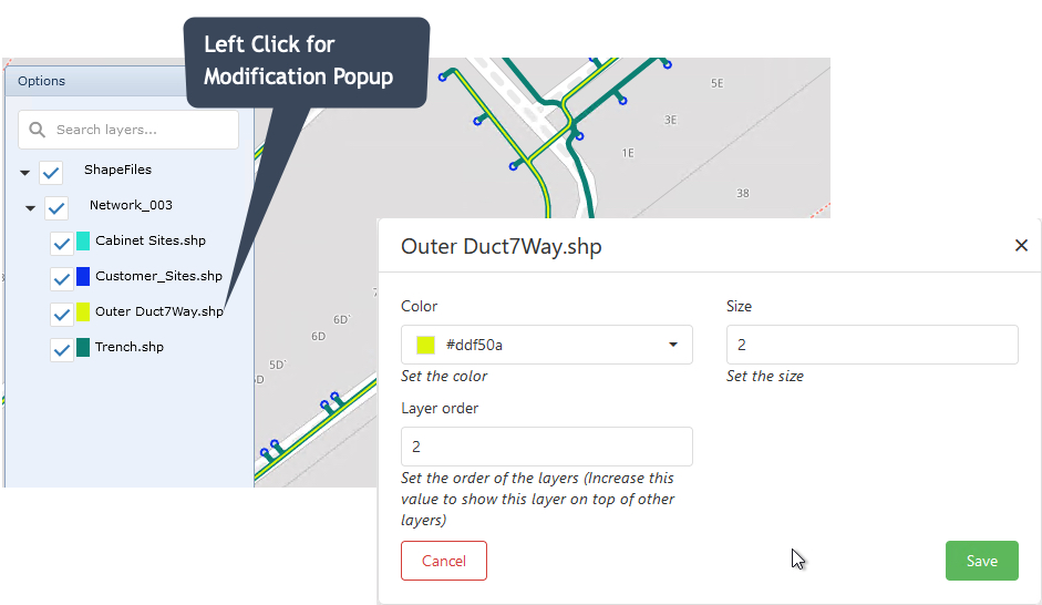
View Element Details
Left click on a Shapefile network element to reveal its information popup window.
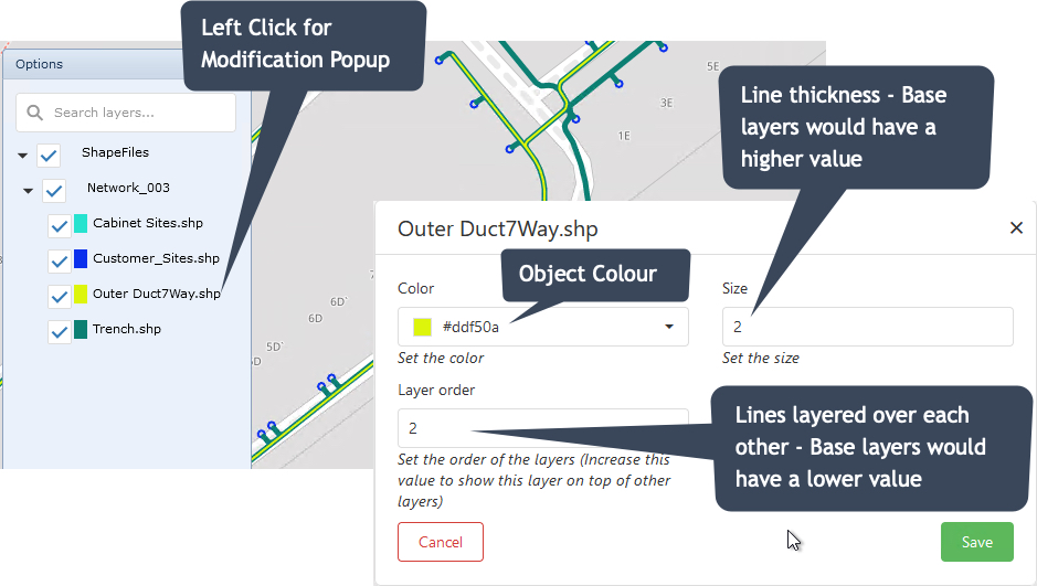
Modifying the look and feel
As network element layers are built up, it is possible to change the look and feel of these layers to enhance visibility and recognition i.e., different thicknesses and colours representing Trenches, Ducts, Cables, and Fiber overlays.
The following screenshots demonstrate how to change Colour, Size, and Layer order attributes for a Trench and Duct run. Notice how the Trench layer (Dark Green) is thicker and lies beneath the Duct layer.