The Butterfly View is a way of displaying manhole ports. In IMS, the manhole is modelled as a Node object. The manhole is first set up in the Equipment Definition as shown in the following screenshot.

This definition is made up of 4 slots - 1 through to 4, and their names represent each side of the manhole.
A slot will then contain a Card Definition which in turn has port templates, as shown next.
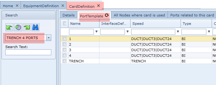
The above example card definition (Trench 4 Ports) represents a Trench that will accommodate up to 4 ducts. Notice that all 5 items are modelled as ports, each with their speed types. In turn, the cable circuits will be associated with these ports to represent the connectivity, using the IMS Circuit object.
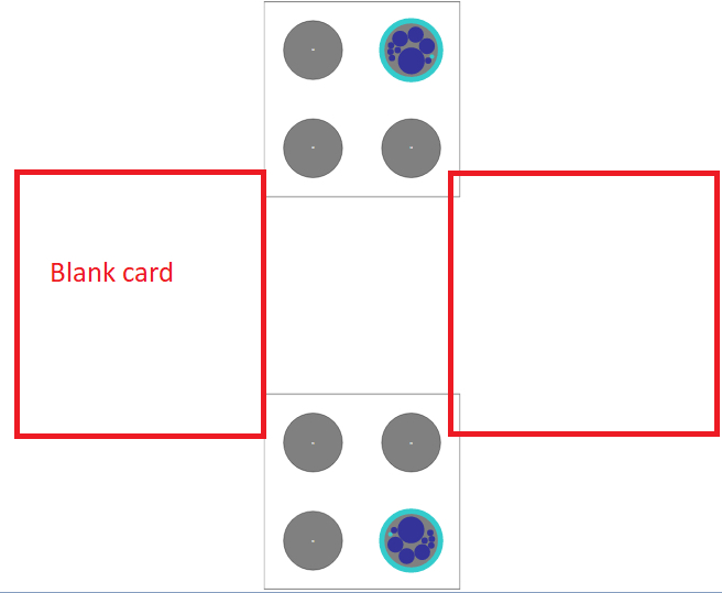
In the next screenshot a manhole instance contains 4 slots with cards, and the one referenced is the West facing side of the manhole. When the blue background (card) is double clicked it will reveal its port details in the lower half of the Node window.
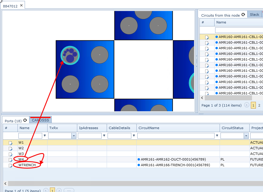
Port W4 represents a duct and has a Circuit associated with it, furthermore it has a light blue circle (user defined colour) which is set in the Products module - under the Circuit option in the IMS Main Menu.
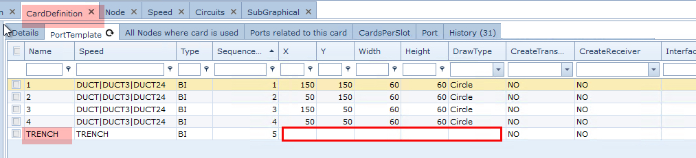
Port WTRENCH represents a trench and has a Circuit associated with it, this is the parent circuit for this west section of the manhole. All other Duct Circuits will be nested inside this Trench Circuit. The WTRENCH port is not displayed graphically as its display coordinates are blank, unlike the other 4 ports - see the following screenshot for reference.
New ports can be added to a card - this is termed as flexible ports and will be described in a section called Adding New Flexible Ports. which can be found under IMS Basics - User Guide : Node : Node Tips
Empty Manhole Side
If a side is not used, then a blank card can be modelled and placed in the appropriate slot.
Empty ports
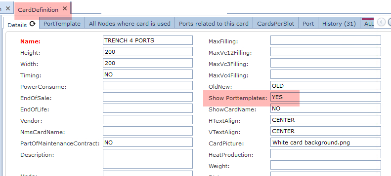
In order to display unused ports graphically, in the appropriate card definition, set the property called Show Porttemplates to Yes
Moving Ports Graphically
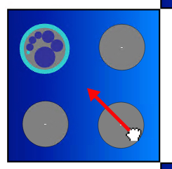
Any port in the equipment display can be grabbed and moved within the Card. Simple click and drag the required port and move it.
Display Angles and Mirrormode
There are a couple of settings in the Card Definition under the CardsPerSlot tab that when set, affect the
display mode of the equipment view
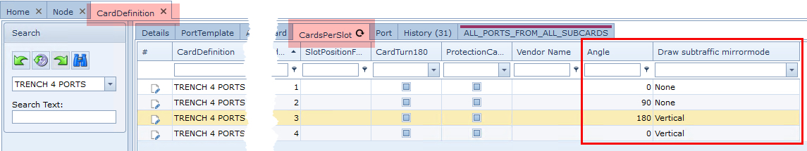
The settings shown above in the Angle and Draw subtraffic mirrormode properties produce a display of slots and ports as follows:
Slot 1 has the default settings applied.
Slot 3 has:
oan angle set to 180 which turns all 4 ports 'upside down' when compared to ports in slot 1
oa vertical setting in the mirrormode property column
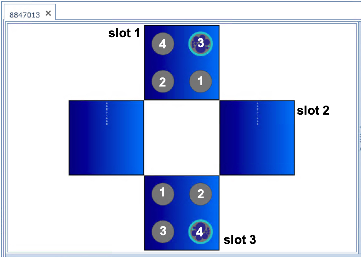
Duct and Cable displays
The displaying of cables in a duct is based on the circuit's associated product and its diameter.

The following objects all have display size related settings:
➢The card Definition's Port Template (tab) has width and height properties for each related port
➢The Duct circuit's Product property has diameter and thickness settings - this Duct circuit connects to the port The Cable circuits in the Duct also have their own diameters, based on their Product properties
In the screenshot above, the largest of the indigo coloured cable circuits (circles) has an associated Product and some of its settings affect how this cable is displayed. In this case the Product called 50MM has a diameter of 50 and an indigo colour set - these details can be seen in the screenshot below.
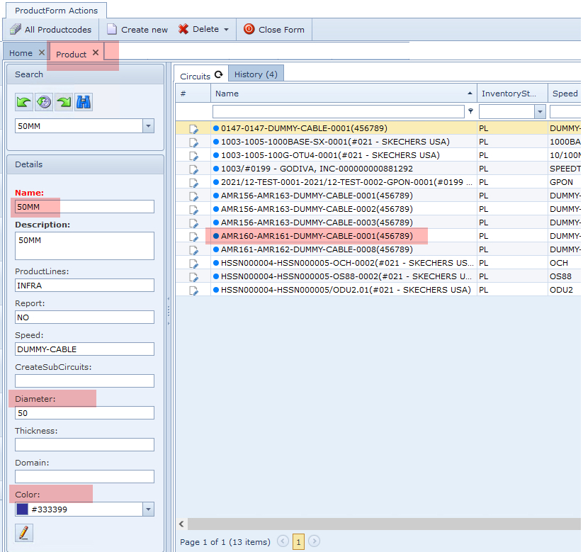
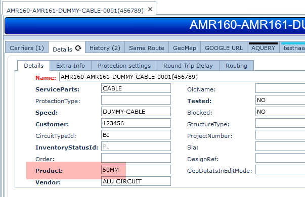
Here is the largest displayed Cable circuit details, showing the related 50MM product.
Butterfly View in Network Maps
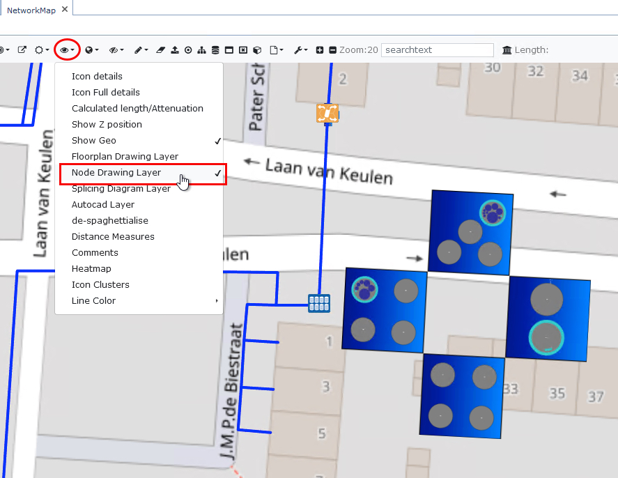
The manhole butterfly view can also be enabled as a layer in the Network Map module.
In an opened Network map, select the Map Display Options icon (eye), and from the dropdown list select Node Drawing Layer
Wherever there is equipment that includes a manhole, it will be displayed alongside its node icon.
The butterfly view is a Scalable Vector Graphic (SVG) file which is loaded as a layer in the map, this drawing can be moved, sized, and rotated by the user, IMS will remember the position for each manhole.