Splice definition
An optical fibre splice is the "permanent or separable joint whose purpose is to couple optical power between two optical fibres, achieved by either a fusion or a mechanical technique" ( International Telecommunications Union - ITU-T).
A Splicebox is a box in which cables and electric lines are joined (spliced) together. Spliceboxes are available in different configurations.
IMS modeling considerations
Spliceboxes boxes are modelled in IMS using the DDF/ODF object, while the Circuit object is used to represent the cable and fiber strand connections to them.
Every segment between ODFs and/or Spliceboxes is a separate Circuit object.
In some locations like midspan joints, fiber cables pass through an ODF/Splicebox where no splicing to other cables is carried out. In these scenarios, fibres are connected to NO-SPLICE patch points in the ODF/Splicebox, and this maintains end-to-end connectivity.
Typically the lower numbered trays in a midspan Splicebox are used for the pass-through fibres of the feeder cable. When any splicing is required from the pass-through fibers, then the upper numbered trays are utilized.

Example of a Midspan Splicebox
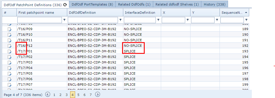
In the example screen shot below, a Splicebox has been configured in a DDF/ODF Definition. Some trays are designated as Splice and others NOSPLICE. Trays 1 to 16 are NOSPLICE trays and trays 17 to 28 are used for splicing purposes.
In pass-through situations where cables are not utilizing the Splicebox trays (cassettes) it is useful to add separate NO-SPLICE shelves to an ODF/Splicebox.
The terms Splice and Nosplice in IMS is a convention that indicates what type of termination a particular fibre cable will be. A Splicebox position with a name that includes Splice indicates that some of the fibre strands of a cable will be dropped off for routing to different destinations and therefore onto different cables.
The term Nosplice indicates that a cable passes directly through an ODF/Splicebox or where the length of a cable reel is not long enough for a cable run and requires joining it to another cable of the same size, or where there has been a full cut in the cable and needs to be re-joined. These are known as Full Splice scenarios.
On the other hand, a Partial or Mid Splice condition is where a cable is brought into a Splicebox, but only a subset of fibers are spliced onto another cable. In this scenario, the main feeder cable should be mapped to the Nosplice tray terminations, except for the subset of fiber strands that are to be spliced onto other cables - these fiber strands should be mapped onto the Splice tray terminations.
It is recommended to model a Splice box to contain termination points that represent Nosplice and Splice terminations, for when a subset of a cable's strands can be spliced, as and when required, to other cables (destinations).
The following diagrams show various scenarios involving Spliceboxes and that can be modeled accordingly:
 Single NOSPLICE Box with No Splice connectors |
 1 NOSPLICE box, 1 SPLICE Box, Nosplice and Splice connectors |
 Single SPLICE Box, Nosplice and Splice connectors |
|
 Dual NOSPLICE Box, Single NOSPLICE Box, both with Nosplice connectors |
|