Opening a Splicing Diagram can be achieved on DDF/ODF type of devices.
The Splice/Patch feature is only available for DDF/ODFs type devices. Further information can be found in the section called DDF/ODF, Patch Panel, Splice Box |

There are 2 methods for accessing the Splicing Diagram feature - Right or Left click on the DDF/ODF device. For the Left click option, first disable the No action on click check box in the Search area of the Network Map |
From the Network Map:
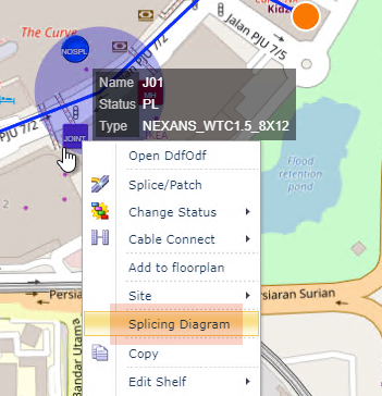
Right click option
▪Right click on the required device (DDF/ODF) to open its drop down list of options
▪Select the Splicing/Diagram option
Left click option
Provided the No action on click check box is disabled in the Search area of the Network Map, the left click action on the required device (DDF/ODF) will also open up the Splice Diagram popup window.