When cables are initially connected to a NOSPLICE box in a manhole/handhole or pole, there will have been no splicing activity carried out.
The following screen shot shows 2 NOSPLICE box cabling scenarios.
1 - The cables are connected to two different NO-SPLICE boxes.
2 - The cables are connected to a single NOSPLICE box - using the front and back positions (connectors)

To splice fibers of a cable (i.e. CBL1 fibers) to an actual splice box, you may have to first disconnect the fiber cables from the NOSPLICE box. This then allows to connect these fiber cables to a Splice box (not shown in the above diagrams) - in IMS the Splice box device can also be known and modelled as a SPLICE box or a Joint (JT).
Accessing the Splice / Patch feature
The Splice / Patch feature can be accessed from:
othe DDF/ODF Actions button bar and selecting the Splice/Patch option
othe Network Map and left clicking on the ODF/DDF icon representing the Splicebox equipment (in this example)
From the Network Map:
▪Right click on a DDF/ODF device that represent the required Splicebox or Joint
▪From the drop down list provided, select the Splice/Patch option
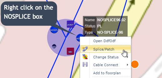
This open up the Splice/Patch popup window.
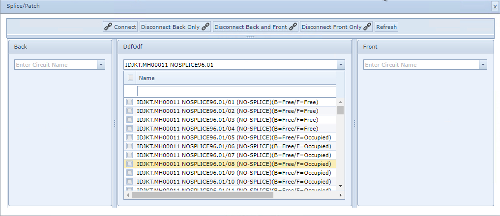
There Splice/Patch popup contains 4 main areas for connecting and disconnecting activities (see next screen shot):
oThe button bar with one connect and three disconnect action buttons and a refresh button.
oThe Back column, with cable search field - contains a list of all the available fiber connectivity details relative to that site
oThe middle column containing the current DDF/ODF device with its splicing/patching names and status (Occupied / Free)
oThe Front column, with cable search field - contains a list of all the available fiber connectivity details relative to that site
Disconnecting Fiber Splices
The following Disconnecting actions can be achieved from the Splicing popup window:
oDisconnect the Back end connector only
oDisconnect Back and Front connectors
oDisconnect the Front end connector only
From the Splice/Patch popup window:
▪In the middle column select the rows by enabling the check boxes that represent the fibers to be disconnected
In the example screen shot below, 4 fibres (/05 to /08) are showing to have their front side connections still occupied, this means that they are still associated with its cable in this DDF/ODF. In order to now splice these 4 strands to another separate device, or tray in the same device, it is necessary to disconnect their front ends.
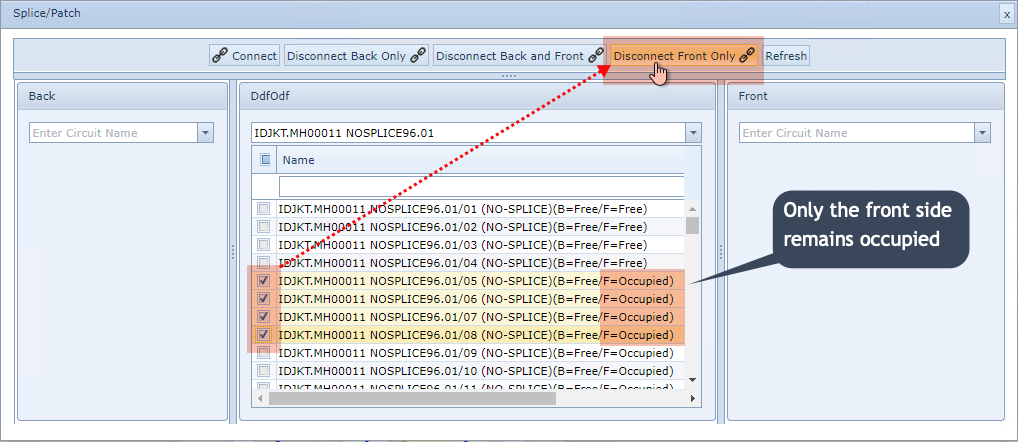
Once selected as shown in the above screen shot - enabled check boxes:
▪Click on the required Disconnect option according to the use case - in this example, Disconnect Front Only option
▪Click on the Refresh option to finish the disconnecting process
The result will look like the first 4 rows, showing their Back and Front connections to be in a Free status, ready for Splicing to another SPLICE tray in the same device or another separate device i.e. a SPLICE box or Joint.
Creating Splices
In IMS, Splicing is achieved by associating cables with connection points in a Splicebox (ODF/DDF). There are two ways of accessing the popup window that allows the Splicing process:
oFrom the DDF/ODF Actions button bar and selecting the Splice/Patch option
oFrom the Network Map (in this example)
•left clicking (with disabled No action on click in Search area) on the ODF/DDF icon representing the Splicebox equipment
•right clicking on the ODF/DDF icon representing the Splicebox equipment and then selecting the Splice/Patch option
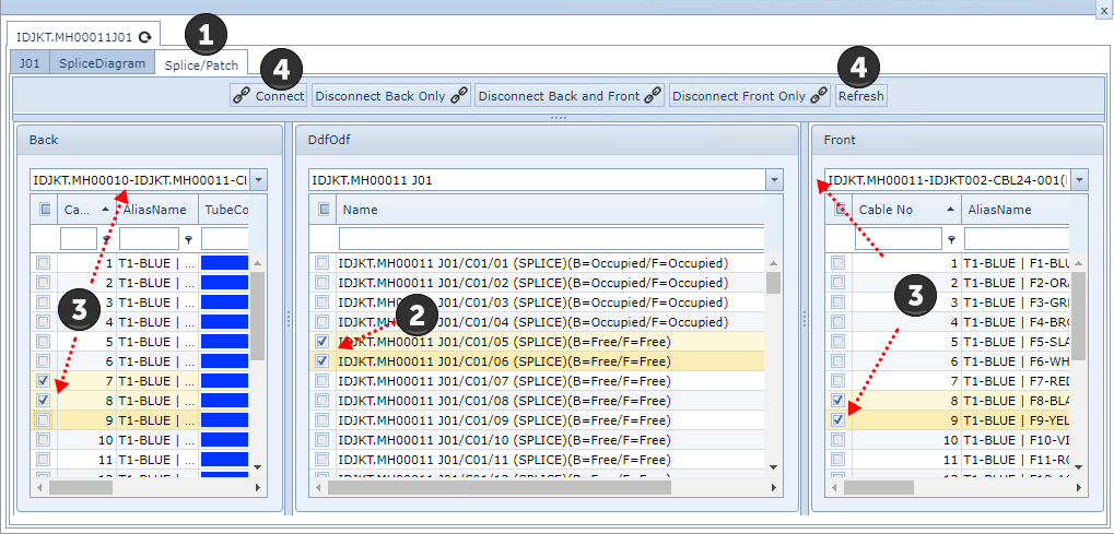
When the Splicing popup window appears the following steps are required:
Selecting fiber endpoints do not have to be in a sequential order, as shown in the above screen shot |
|
Select the Splice/Patch tab - not required if left click option followed as mentioned above |
|
From the middle panel, select the required splice point ends in the tick boxes provides |
|
Select the appropriate cables from the drop down search fields followed by selecting the required (free) fiber strands from the check boxes provided |
|
Click on the Connect button to form the Splice relationship and then the Refresh button |
The result is both Front and Back connector points will show as Occupied.